How I ended up reverse-engineering (yet another) quadrocopter and replacing the proprietary firmware with open source to turn a product well meant into a package well done
Ten episodes… Initially I was planning for three, maybe four parts: An introduction, the hardware, the configuration and finally the maiden flight. And I have barely touched the surface of the technical details, leave alone a step by step tutorial for anyone to follow through.
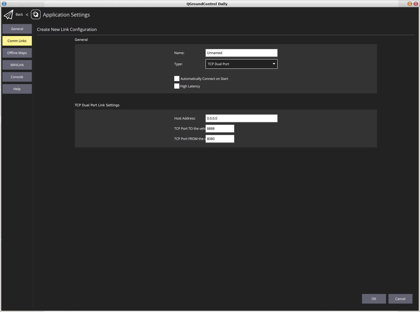
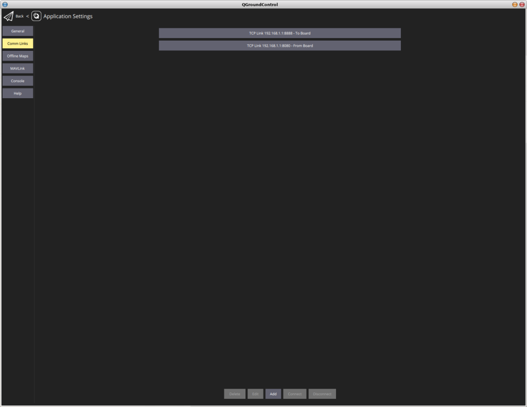
As we already discovered, QGroundControl has many options for connecting to a vehicle and one of them is via TCP. Unfortunately, this is only limited to a single port connection for both, up and down stream data, while the SimToo Moment uses two ports, one for each direction. And again, the well organized and documented source code made it quite easy to add the new feature.
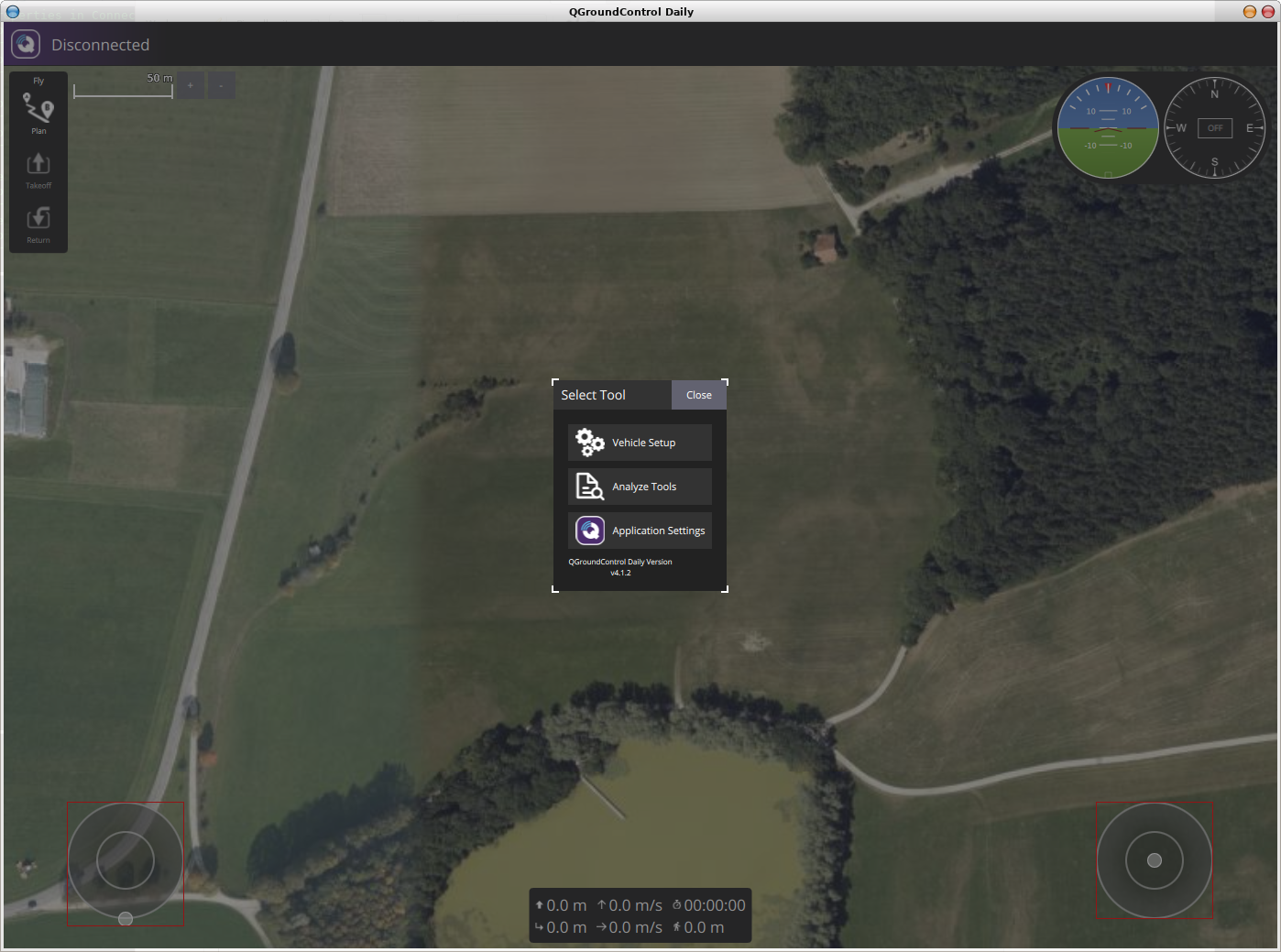
QGroundControl…
…with the tools menu now in the center…
…a new dual port TCP feature…
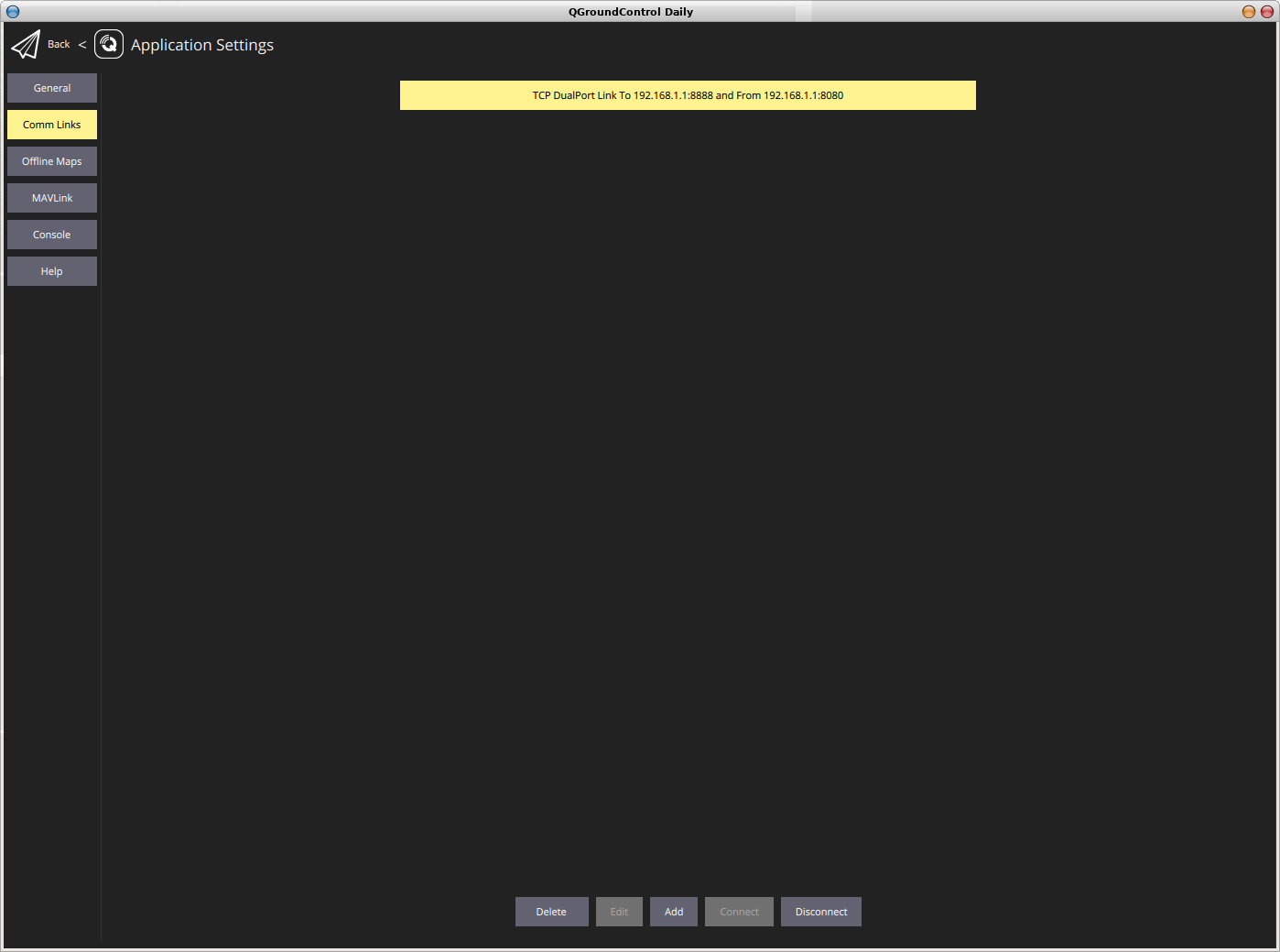
…first attempt always fails…
..reconnect…
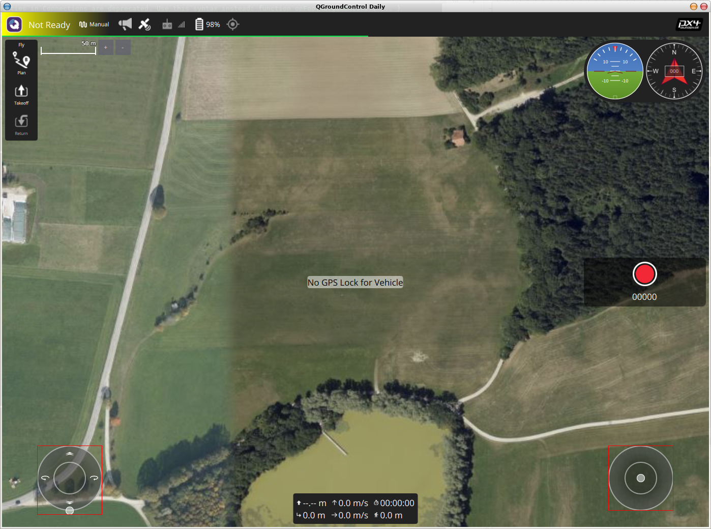
…connecting…
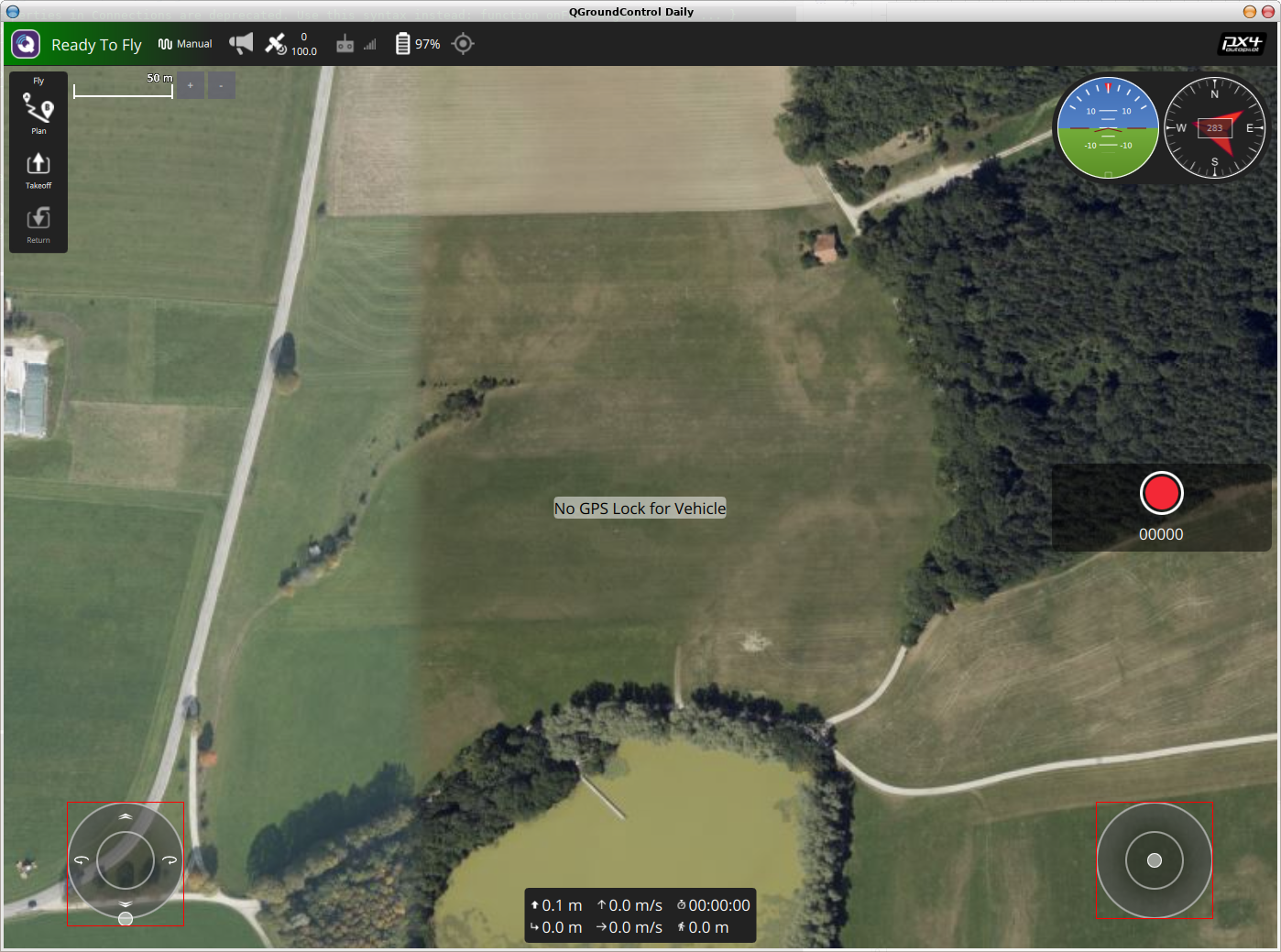
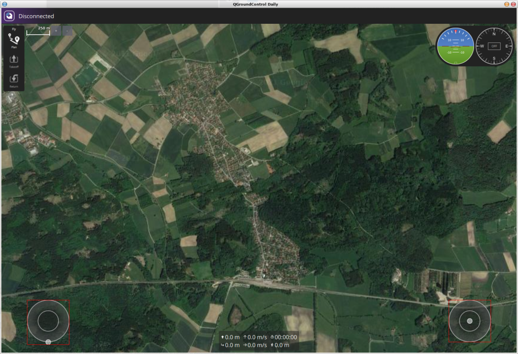
…ready to fly…
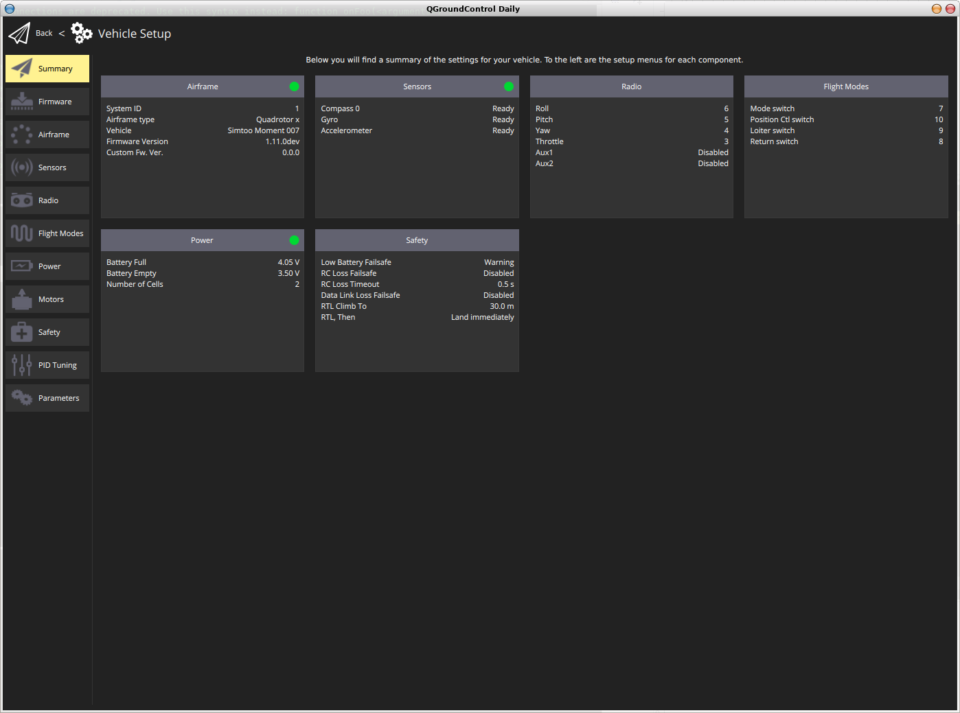
…vehicle parameters…
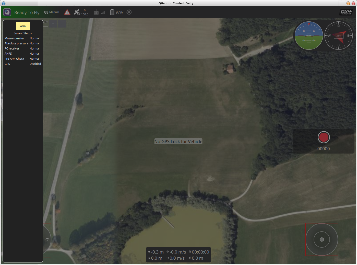
…arming.
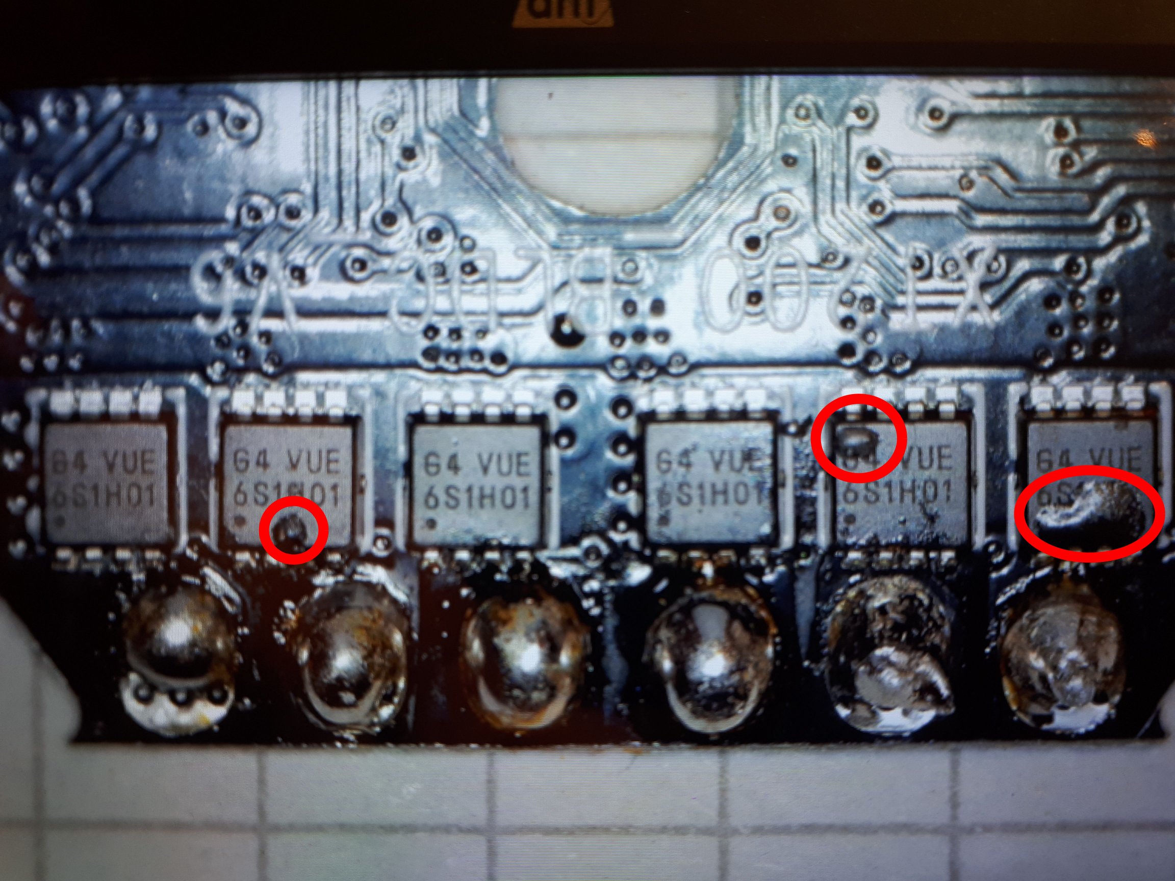
A quick test of the PWM outputs, just to make sure that we wouldn’t fry the FETs again, got me confident enough to solder the motors back and put everything together again. I then added the tuning parameters I found in the Crazyflie configuration to my firmware and… voilà. The package was ready for a first take off.
Maiden Flight in a Confined Area
QGC also has the feature where you can control a drone with any kind of joystick, preferably a game pad, since they come with at least two analog sticks and a bunch of buttons just like on a classical remote control for things that fly. And it was working fine in the simulation, but somehow did not like my dual port connection. As soon as I connected the game pad, the port going to the drone was closed, no matter if it was a wireless controller or one with a cable. Another thing I saw (also on the single port TCP, so it wasn’t me, who broke it) was the port only being opened on a second attempt after connecting to the WiFi.
A whole other topic is the optical flow / ultrasonic distance sensor, which I am presently not using. Aparently I deleted the firmware on the first board (which was the reason why it didn’t work in the second drone), probably due to leaving “remember my choice” checked after unlocking the FMU. Fortunately, the board has a debug interface, which can be used to create new and thus even PX4 conformant firmware. But that shall be a new project.
For now I am happy with the results: The proprietary firmware on the FMU has been replaced by open source and so has the application for controlling it. I will do more flight tests outside and try to capture some videos and then… I can maybe go back to the original project. Or use the incoming video stream for some AI recognition stuff. Or create a swarm of drones. The sky is the limit and even if it gets too small, there is still space and other planets to fly to and on.
How I ended up reverse-engineering (yet another) quadrocopter and replacing the proprietary firmware with open source to turn a product well meant into a package well done
Back in the days an electric battery was a simple source of power with two terminals, positive and negative, that could be used “[…]for powering electrical devices such as flashlights[…]”, walkmans (or is it -men?) or R/C toys. The biggest issue with them was their irreversable nature, which means once they were done giving power, they were done and went on the ever growing pile outside the city, adding to many forms of pollution.
Fastlane to the no fly list.
Then came rechargable batteries which are now commonly lithium based. Each generation more powerful and longer lasting, but also more dangerous and complex. They require not only just some power to be charged, but need to be fed wisely with cell balancing and such, which ultimately means, there is logic involved, even in the process of giving power.
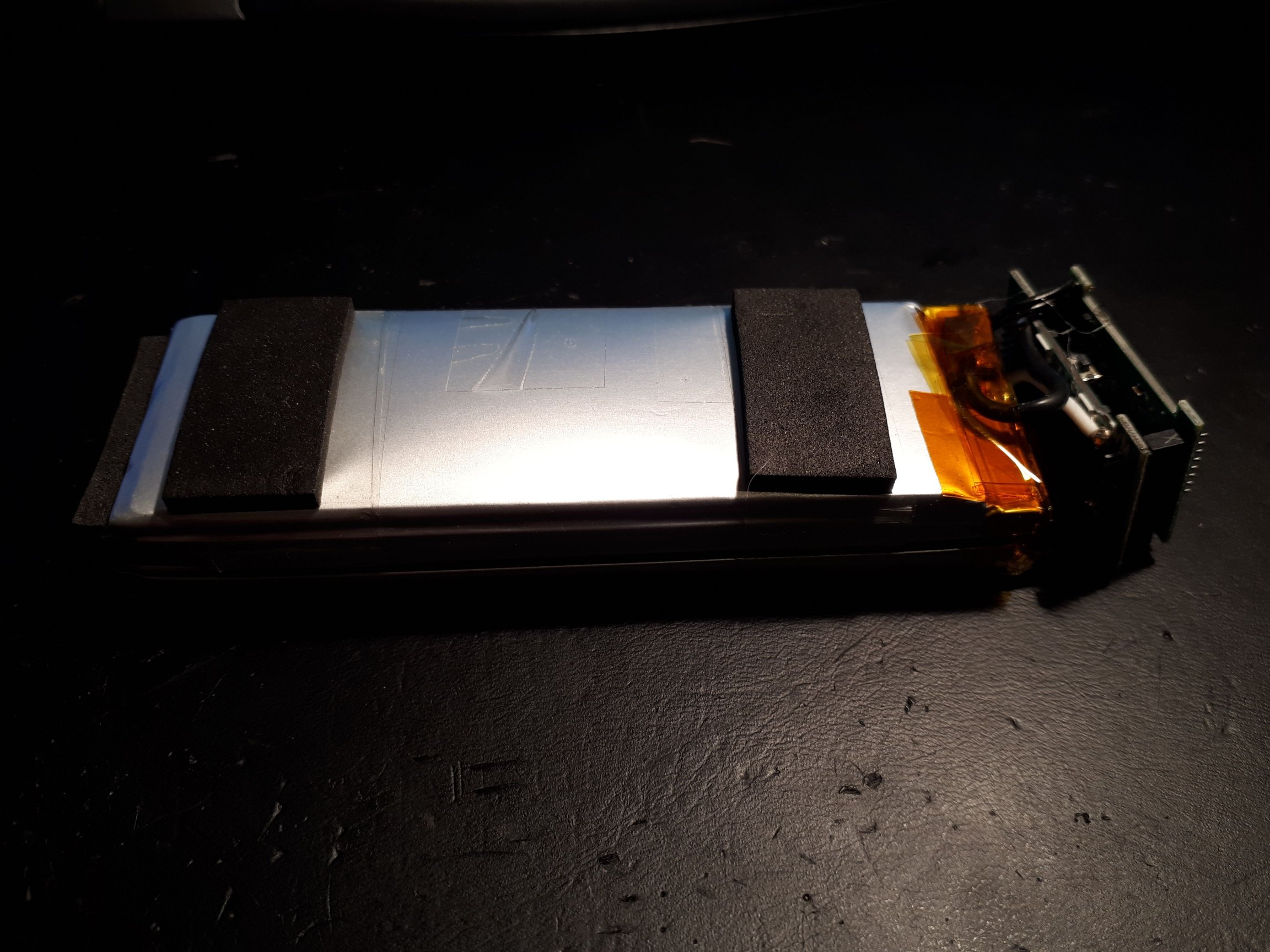
Both drones came with two batteries
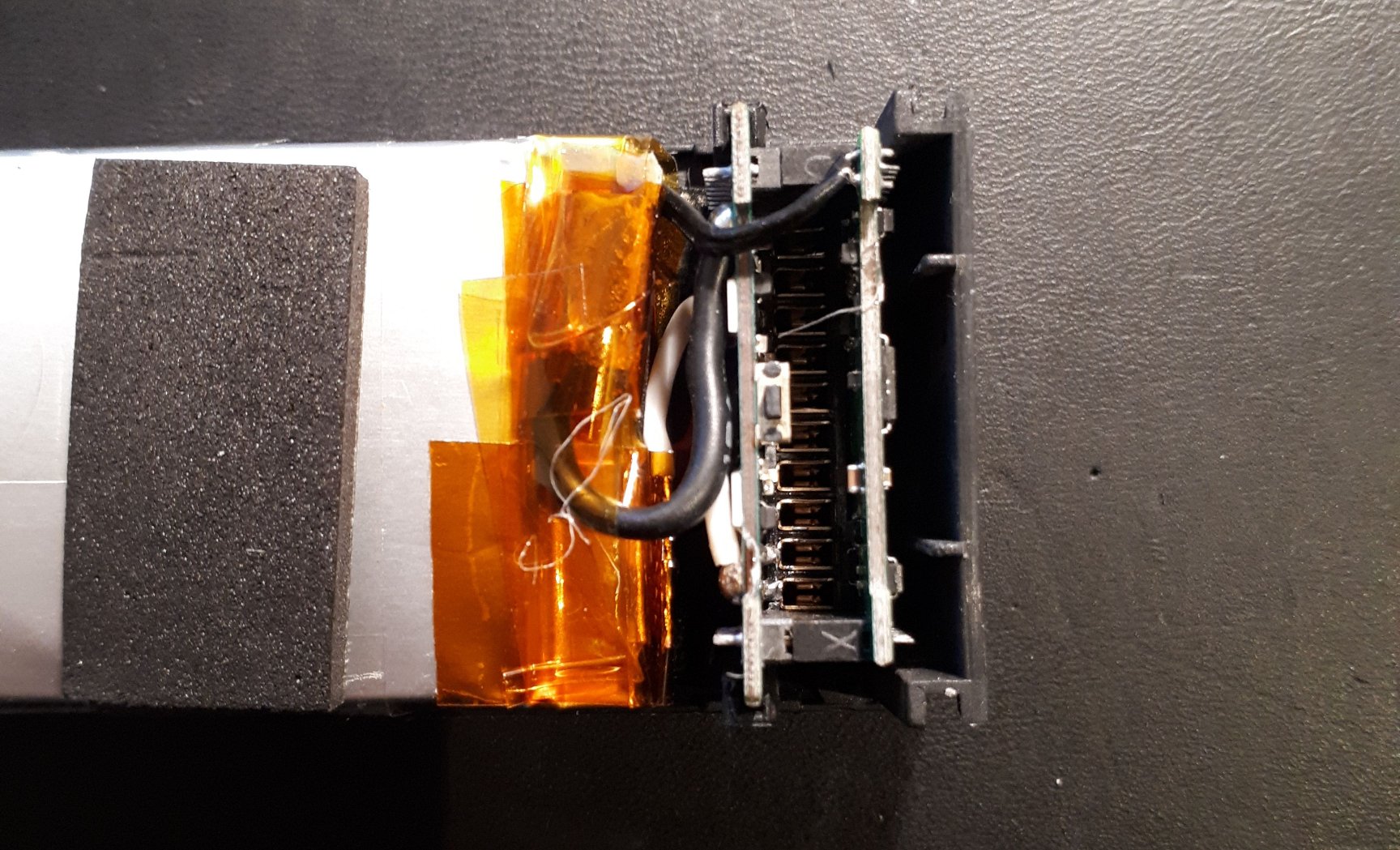
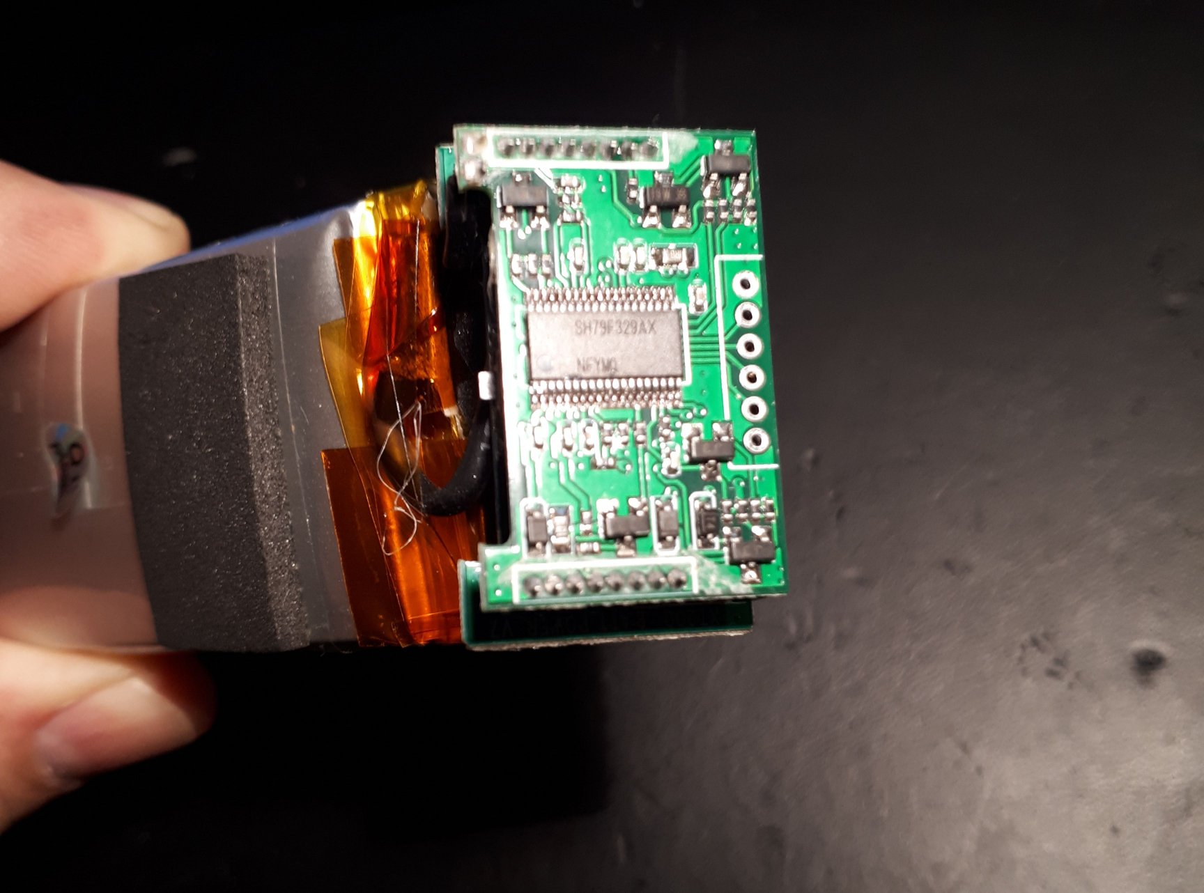
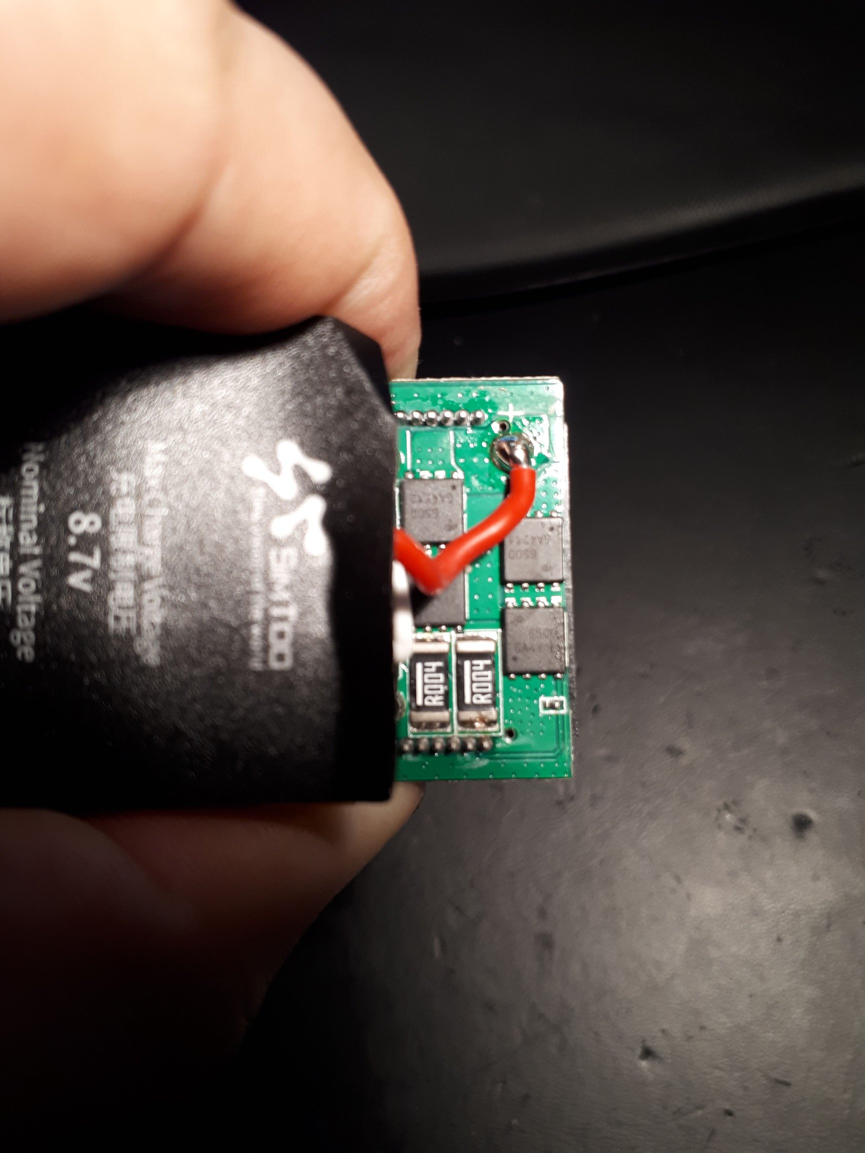
In most UAVs, you don’t just fit the battery and flip a switch to turn on the aircraft, but you install and turn on a power plant, which has become a line replaceable unit with its own brain. The batteries of the SimToo Moment Hoshi 007PRO Airselfie Drone come with two cells at 4.35V each and a battery management system (BMS) built around a Sinowealth SH79F329, which seemed to be a common MCU for rechargable batteries a few years ago, but with very little documentation and worst of all: with firmware.
Two cells…
…stacked BMS PCB…
…front…
…and back
Why is that a bad thing? Well, other than with stupi… uhm… simplistic sources of power, where physics and chemistry define the limits, it is now also a piece of software that has a say on wether or not there will be energy. This can be an advantage in terms of cell care, making the battery last longer or even prevent hazards, but it is also very dangerous when it comes to things that fly, where cutting the power in mid-flight almost 100% leads to disaster.
With the SimToo batteries this seems to be the case at exactly 15 minutes of runtime. Yes, you read right: During my tests, the batteries turned themselves off after 15mins without any warning or necessity due to e.g. low power or other outside factors like temperature. Just as an example: The latter used to be an issue for the DJI TB50, a professional grade supposedly smart battery designed for the Matrice 200, but also used by other drone manufacturers, who wondered why their precious pregnant ducks would drop out of the clear blue winter skies when operating below 15°C even though they had four(!) of them on board. While there seems to be few good reasons for such a mechanism, just cutting the power is a bit short sighted. So was blaming the lowest paid employee in the development team, who constantly warned about the side effects of such practice, but that’s war history.
Where were we? Yes. Smart Battery. As we already have guessed by taking a closer look at the hardware, two traces of the power distribution board join the club of devices tied to the I2C2 interface on the FMU, along with the GPS (which doesn’t seem to be used), the magnetometer (which is missing in the second drone, where the sticker on the PCB says V1.2 instead of the V1.1. Guess, I was lucky to have it in the first one) and the flash memory. Taking out the disconnectable variables like the GPS, magnetometer and even the battery by replacing it with an external bench power supply and then adding the peripherals one by one while listening to the bus puts us into the position to see which device IDs are being talked to.
Device ID
Device
0x0B
Battery
0x1E
A983 Magnetic sensor
0x50
F256I Flash Memory
Device IDs on I2C2
We already have dealt with the magnetic compass and the flash in part 6 of this series, so all we need to do is listen to the ID 0x0B, a name well chosen for the battery.
Battery ID readings at 2Hz
In the data stream there is only three registers being read by the FMU at a rate of 2Hz: 0x01, 0x03 and 0x12. Since we are dealing with a battery, the first guess would be: State of charge (SOC), voltage and maybe current flow or temperature. But I was wondering, can that be all? So I created another simple project with CubeIDE and STM32 HAL to iterate through the registers from 0x00 to 0xFE and find responses on more than the above mentioned three.
With four batteries to measure and compare, it was quite easy to figure out the registers. Playing with the values and comparing LSB / MSB interpretation resulted in the follwing:
Register
Length
Meaning
Unit / Content
0x01
2
Voltage
[V] * 1000
0x02
2
Voltage
[V] * 1000
0x03
2
Status¹
0x04
2
Temperature(?)²
[°C] * 100
0x07
2
Manufacturing Related(?)²
0x0C
2
Voltage Cell 1(?)
[V] * 1000
0x0D
2
Voltage Cell 2(?)
[V] * 1000
0x10
2
Max Charge Voltage
[V] * 1000
0x11
2
Rated Capacity
[mAh]
0x12
2
State of Charge (SOC)
[%]
0x13
2
Remaining Capacity(?)
[mAh]
0x14
2
Rated Capacity Related(?)
0x15
2
Remaining Capacity Related(?)
0x21
11
Chip Manufacturer
Sinowealth
0x22
2
?
0x23
5
Product Name
XT20
0x24
7
Cell Type
LIPOHV
The rnterpretation of the readings
So there seems to be quite a bit of more information that can be retrieved from the battery.
Registers 0x01 and 0x02 were quite easy to figure out by just measuring the voltage on the battery poles. It is surprising, though that there is two registers providing the very same data.
What seems to be the status register at adress 0x03 was zero for three batteries and only had a different value for battery no.3, which I had running on the second drone until the SimToo App gave me a warning that the SoC was below 15%. This is also how I figured out register 0x12 by comparing the indication on the App with the values.
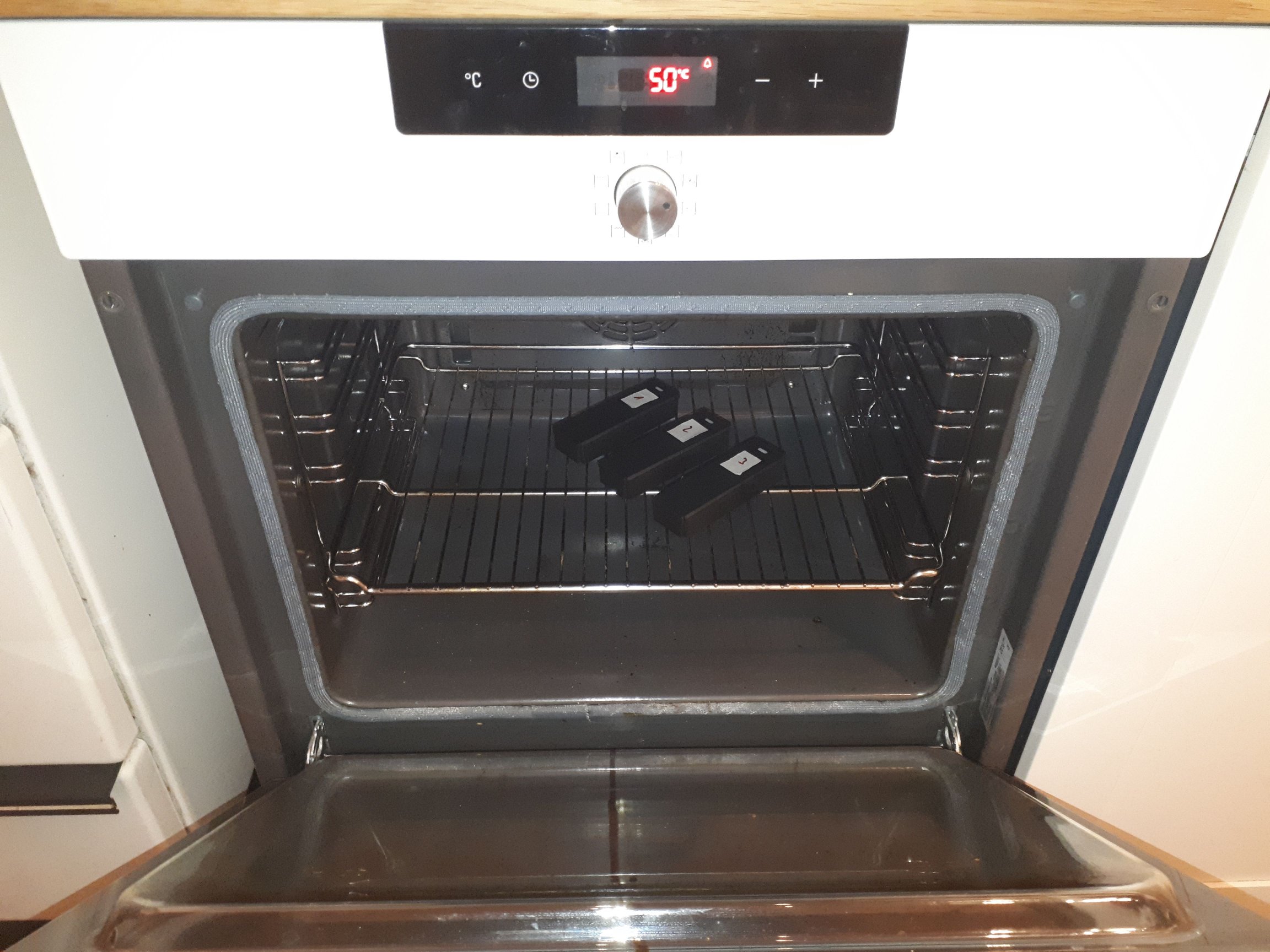
You’re hot…
…and you’re cold…
Register 0x04 is not confirmed, yet to be the tempearture register, even though I have a strong indication that it might be related to it, after putting the batteries into the oven and the freezer for testing and comparing values.
0x07 seems to be related to the manufacturing charge, as the values differed in pairs. Two batteries returned 0x94 and the two others 0xd4. Unfortunately I decided to mark them only after mixing them and there is no sticker with a manufacturing date or serial number on them, so we cannot be 100% sure if the pairs are really what came with the packages.
0x0C and 0x0D are intelligent guesses and match the total voltage of 0x01 and 0x02 when adding them up. The fact that 0x0E and 0x0F are empty could mean the BMS would even be capable of managing four cells, something I haven’t checked on the PCB, yet.
The values in registers 0x10 and 0x11 are the same for all four batteries and also match what is written on the casing.
0x12 was confirmed by the App, as stated above. A little fun fact: the App would take quite some time to display the SoC, if ever. Didn’t check, though, if it was just missing in the data sent by the FMU or if the App just decided not to show it.
0x13, 0x14 and 0x15 seem to be related to the capacity of the batteries.
0x21 contains “Sinowealth” spelled in ASCII and provided the clue on what the SH79F329 on the PCB was referring to.
0x22 could have something todo with the hardware / software revision, but is also unconfirmed.
0x23 is the ASCII representation of the drone hardware, as it can be found on the PCBs, too.
0x24 refers to the type of cells, in this case LIPOHV, which btw is not written on the batteries themselves, but a common choice for R/C devices due to various reasons.
From an earlier project I know that the DJI battery station for the TB50 communicate with the batteries during charging, e.g. to display the data above and whether the battery is in heating mode or such, so I wanted to know if it also is the case for the SimToo charger. The answer is simple and straight forward: No. The charger doesn’t check any of the info that could easily be provided by the power bricks and instead remains silent during the whole charging process. The question is, would the consumer or at least the charging process benefit from such a communication, like in having a small display showing the status or keeping some persistant data about the charging cycles and such on the battery… There is always space for improvement, even in the prettiest design.
That’s it. Another mystery solved and after trying and testing the findings on a basic CubeIDE project, it has found its way into the drivers’ section of my branch of PX4.
How I ended up reverse-engineering (yet another) quadrocopter and replacing the proprietary firmware with open source to turn a product well meant into a package well done
If you wish to understand the universe, think of energy, frequency and vibration. Nikola Tesla
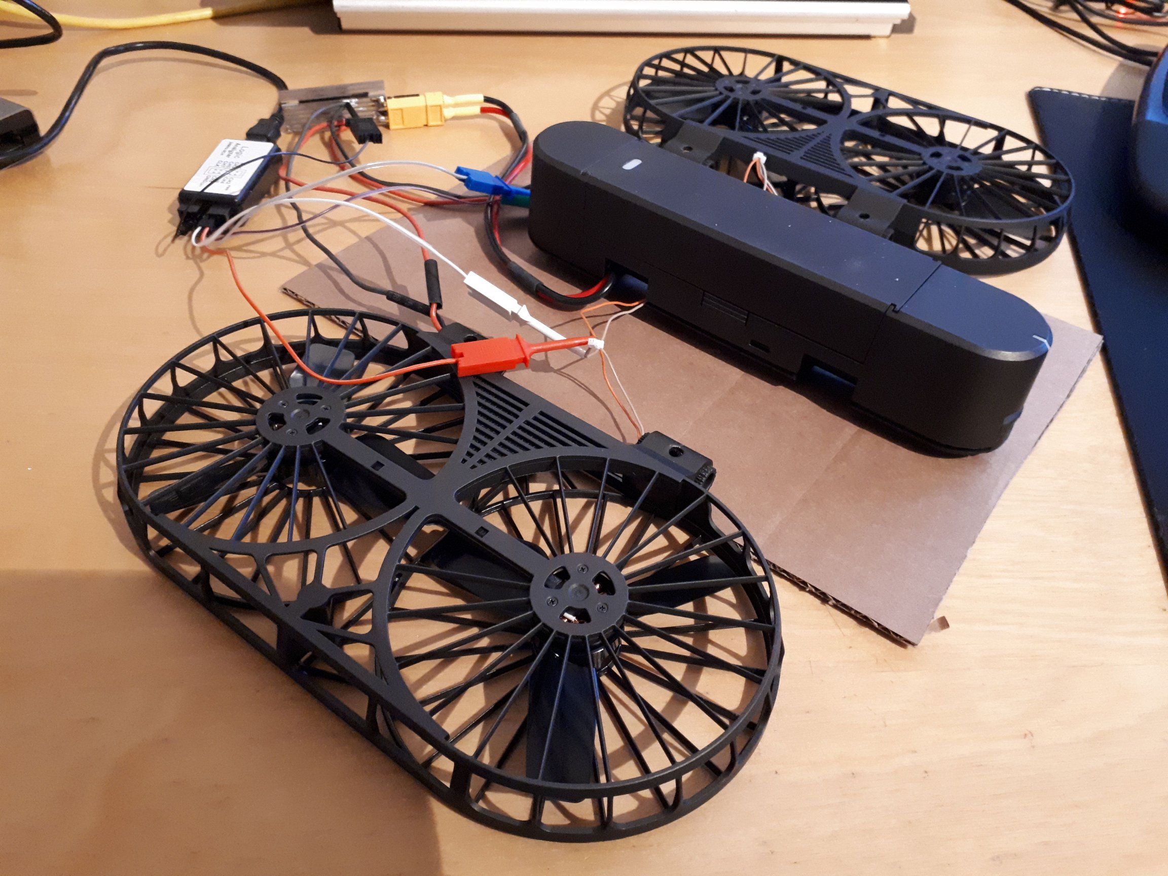
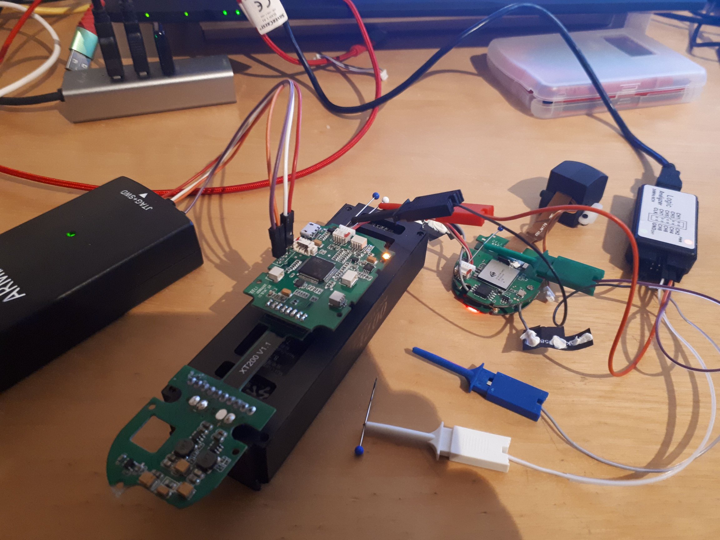
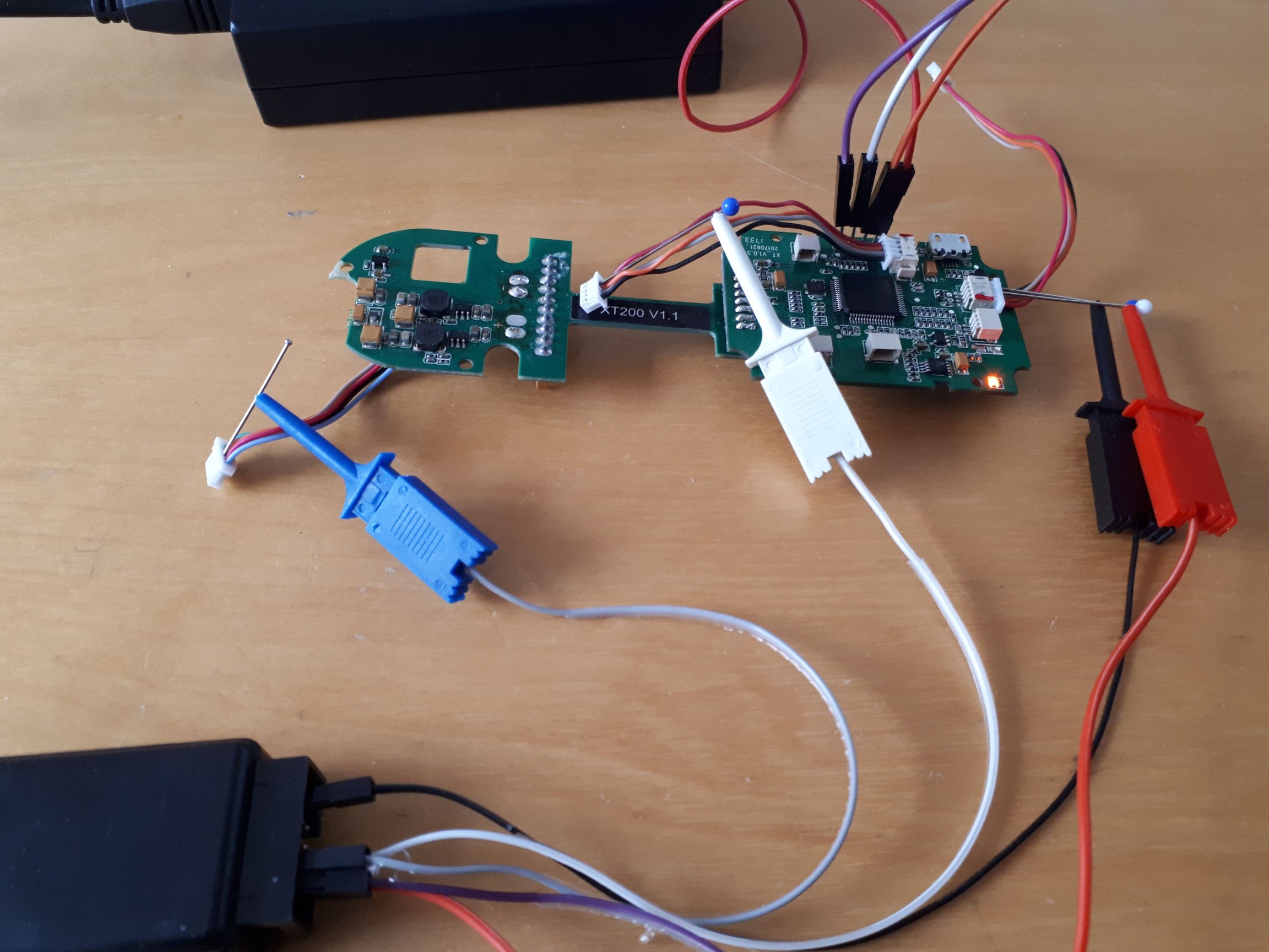
The new drone barely arrived and was already taken apart to become an organ donor as well as a reference system. We knew from the first trials with the pixhawk and the SimToo ESCs, where the latter ended up in smoke, that the parameters definitely needed some adjustment. But how to collect the data with running motors and a logic analyzer attached? To prevent it from flying away with the all the needles and pins, operating the drone upside down was not an option because the app didn’t allow it. Tieing it onto something wasn’t much of option either so I decided to go for a compromise of these two: putting the wings upside down, while the body remained in a normal position.
After everything was finally set and hooked up, the drone still wouldn’t turn on the engines and instead show a message about “incorrect data” and “restart drone”. I was going back and forth and even got a bit worried that the FMU might have been broken from the start, finding some evidence of thermal mistreatment (which wasn’t the case with the first drone), but it turned out the new FMU didn’t like the optical flow board from its sibbling. But after installing the original board, it accepted the commands and let the engines run to provide the data we wanted: Frequency and min / max pulse width of the PWM signal.
A quick export of the recordings, some calculations and sorting on a spreadsheet provided some charts and the following data:
Period / Frequency
Idle Pulsewidth
Max Pulsewidth
2.5 ms
1 ms
1,844 ms
400Hz
40%
~73%
The Barometer
There were two more components that we didn’t have figured out, yet: The Baro on SPI2 and the question on how smart the battery connected to I2C2 was.
The Baro IC
Unfortunately the marking on the baro IC did not please the gods of finding stuff on the internet and so they did not spit out any datasheets or code. Not even the reverse image search rang any bells other that the unhelpful generic ones. This time not even the drivers already included in PX4 could breathe any life into the frog inside the tiny package and so I had to make sense of the recordings all by myself. Challenge accepted.
Only a few sessions of putting needles into connectors and recording some logic had me figure out quite a bit, though. I started with recording the SPI by holding four tiny metal rods with one hand and turning on and off the battery with the other. If I had known I would be doing this for more than just the initial recording, I would have just fired up my 3D printer and build this acupuncture apparatus, going for a walk while waiting for the results. Anyhow, the fiddling around was totally worth it for it shed lots of light into the dark of the rabbit hole.
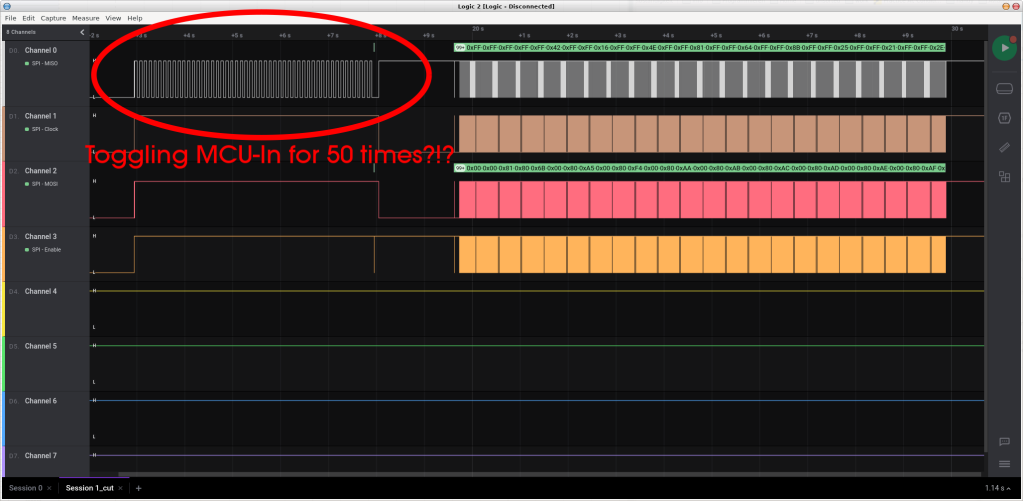
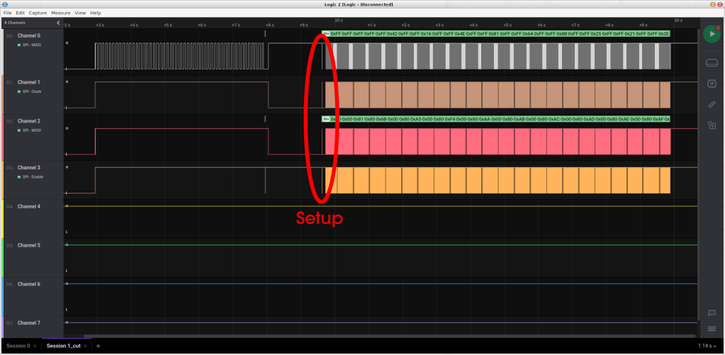
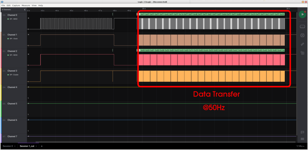
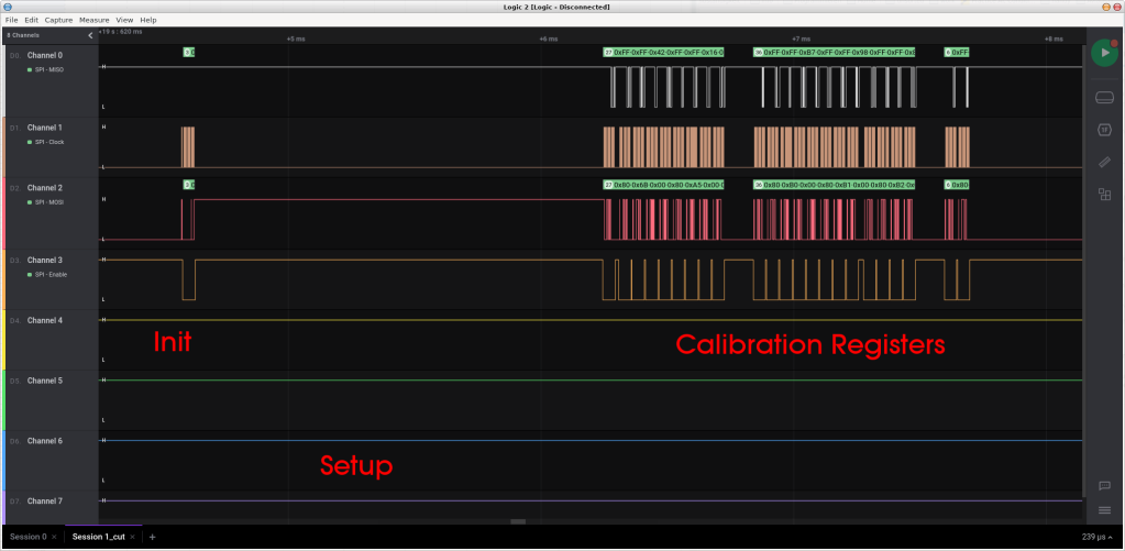
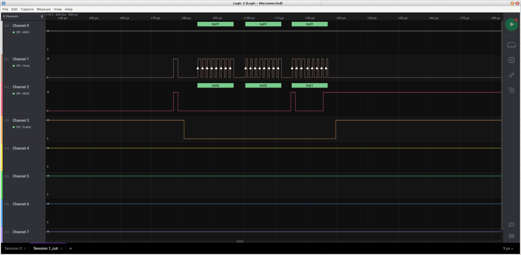
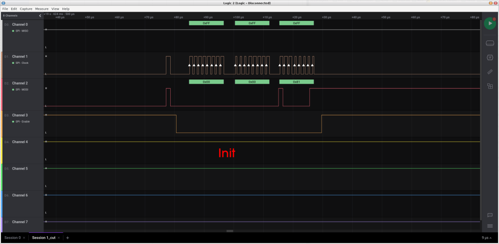
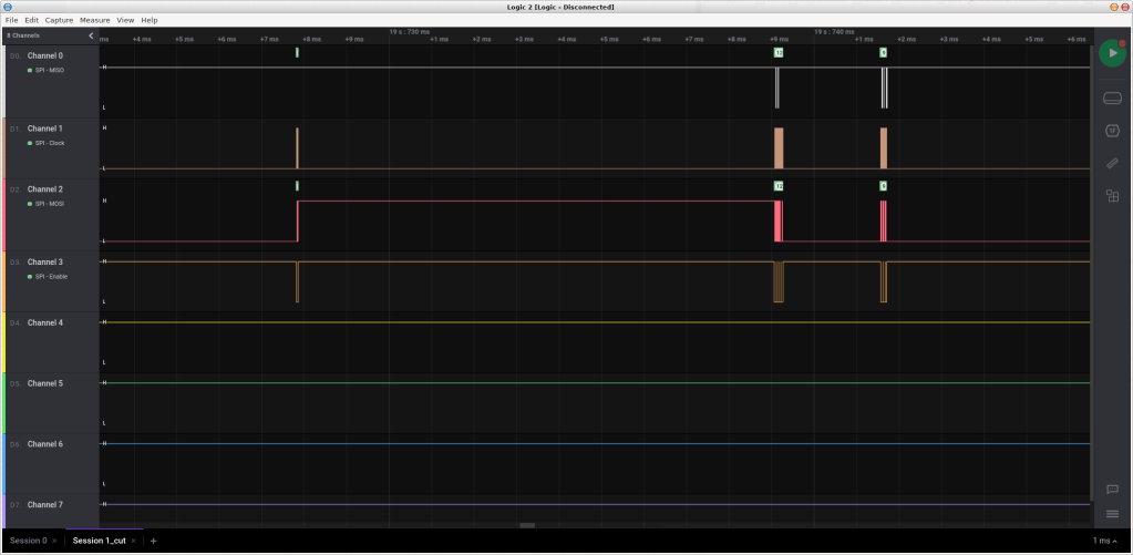
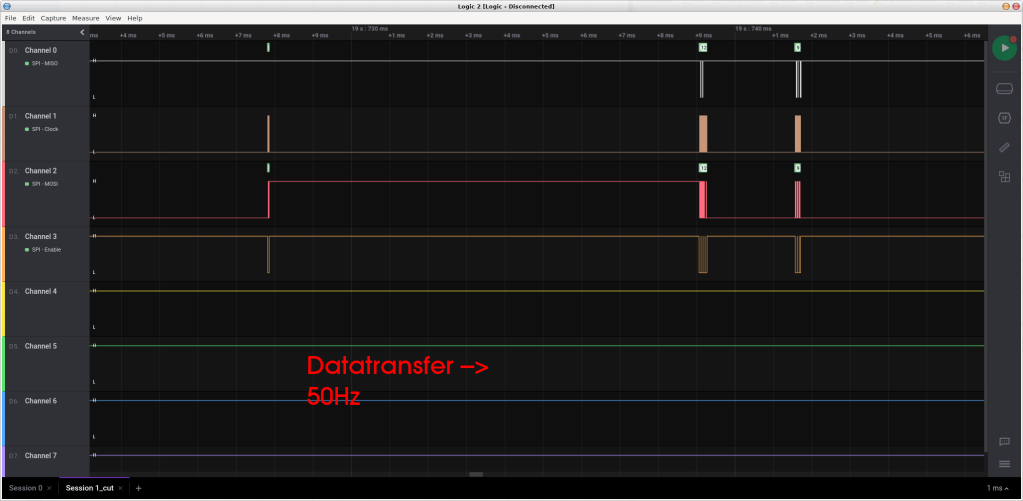
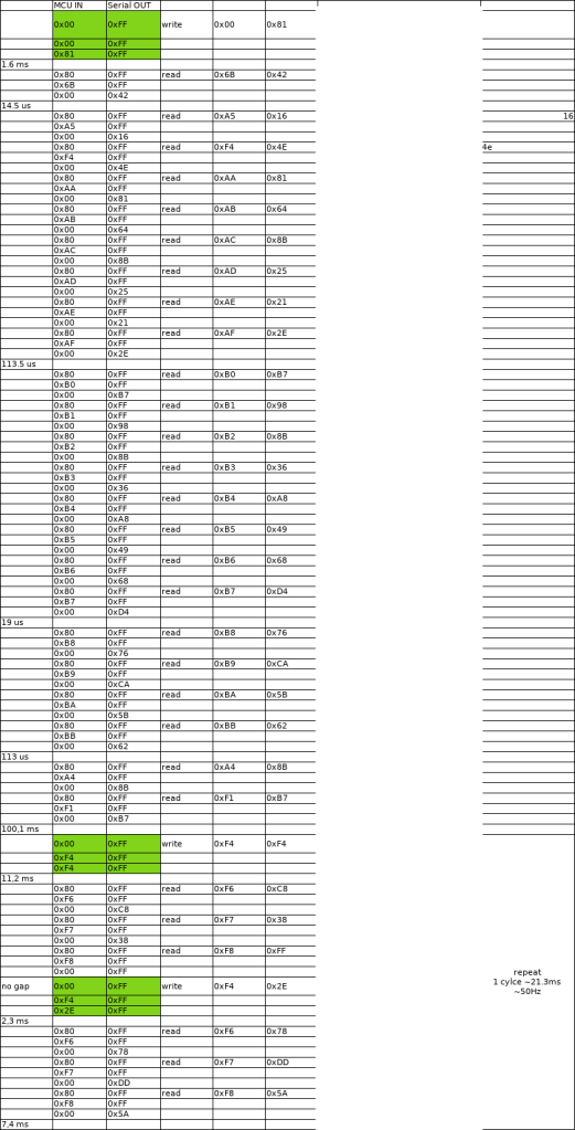
To make the long story short: The original firmware, which was still on the second drone, started talking to the baro IC by toggling the MCU-In-Serial-Out (not only political correct, but also “don’t give words the chance to mess with your head by keeping cruel ideas from the not so far past alive”-version of MISO) 50 times, before sending the actual init command, along with reading the calibration registers and finally starting the data transfer at 50Hz. Most of the baro ICs seem to be quite similar, I mean, why should they do anything else than measuring the temperature and the pressure and calculate in mind bending ways the altitude from both. As a matter of fact, when looking up what seemed to be the chip-id (0x42… ooh, this is an interesting sensation), I happend to surface not only one, but two quite similar datasheets: One was the seemingly Taiwanese based “Formosa Measurement Technology” FMT-FBM320 and the other one the Germany based “Angst+Pfister” or now “PewPewPewatron” (with only one Pew) PBM210. It is beyond my imagination and even though I fought hard not to overthink the similarities, comparing release dates and wondering why… 210… 320… same pictures… no, no, no. Focus.
And as it so happened, our Asian friends have a github repository, something I haven’t seen so often being run by a manufacturer of a mass product. And when digging even a bit deeper, you can find quite a few other repos having drivers for the FBM320.
So getting the MCU we freed of its proprietary burden to talk to the IC was not much of a problem. For quick results, I started with a CubeIDE generated project based on the STM32 HAL library, just to test the SPI communication while also limiting the unknowns in the equation when trying the same with a full blown autonomous flight stack coming along. The thing that I learned was this:
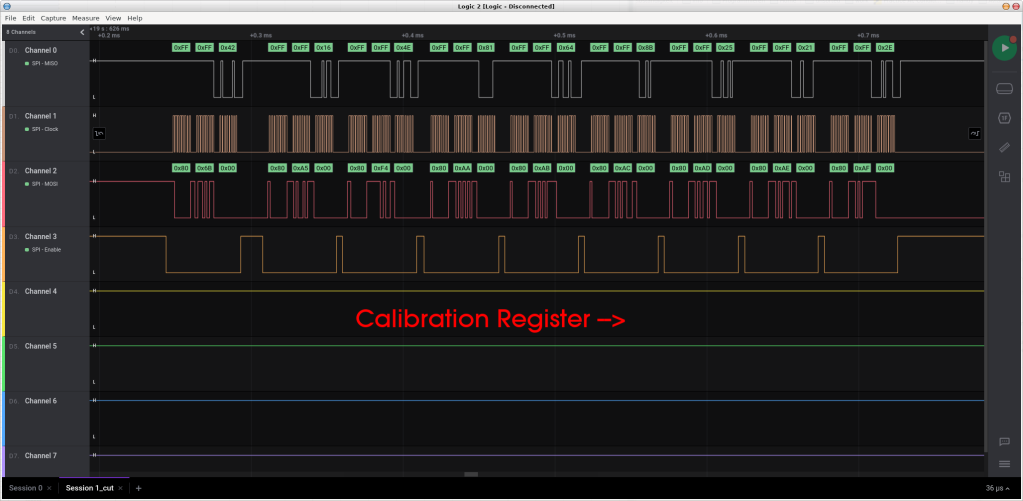
The IC does respond quite well to the basic driver commands like initializing and reading out the calibration registers
The calculated hardware version is 5, which doesn’t seem to be an option in the FBM320 firmware (only within the case “default”), but is in the FBM325.
While the FBM325 calculation would be totally off in both, the altitude and temperature, the drivers I found in the other repos containing the FBM320 at least got the temperature right
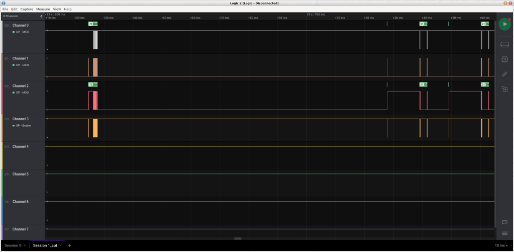
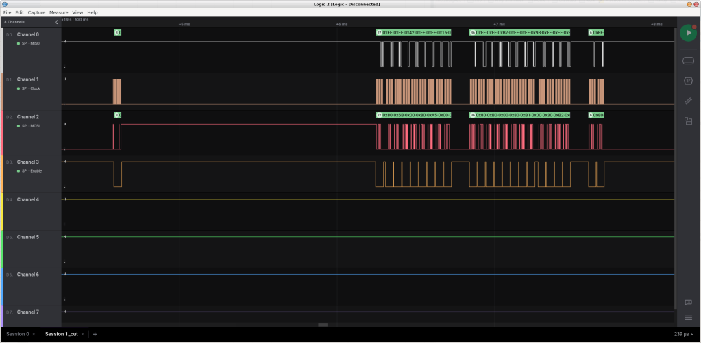
The clearer picture of what was going on on SPI2
Since this is already part 8 of what was supposed to be a quick “flash and fly”, I won’t spend much time on trying to figure out the correct calculation procedure myself, but hope the community might have the time and is willing to support here, so I can add this to the driver package. The quick-solution project will be available in my github account soon. Who was I trying to fool… Of course this was a challange too tempting to ignore and on I went. And in the end it was only a matter of LSB vs MSB, which got obvious looking at the meandring values of temperature and pressure and the way bulk-reading values from the chip went.
After everything was corrected in my CubeIDE project, I added the resulting driver to my branch of PX4 and was vastly surprised: Not only did the driver get me a sense of rising and falling for the drone, but also much more data displayed on QGC. As it seems, the baro values were required for the estimators. This is why on my pixhawk the artificial horizont was working from the beginning even via the telemetry dongle and on my SimToo, I always had to start it manually. Now with the baro working, the data is even coming via the WiFi connection. What a blast!
And then there still is the battery to be figured out…
How I ended up reverse-engineering (yet another) quadrocopter and replacing the proprietary firmware with open source to turn a product well meant into a package well done
Graphics driver on my PC getting stuck during video test
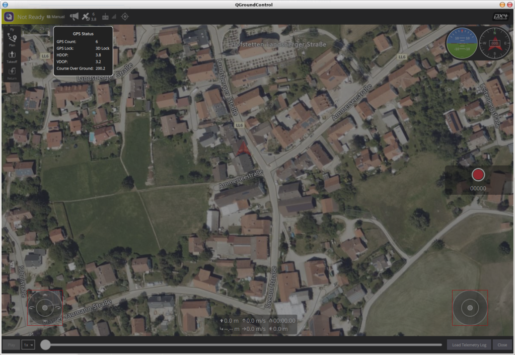
As usual when entering the final approach, things start shaking up a little. In my case it was the video coming from the drone. As we have seen in the network data, the WiFi access point not only lets us talk to the FMU, but also provides an RTSP stream of the camera footage. But it seems to be a bit picky when it comes to initialization. Opening the stream just with the IP address and port seems to crash the AP. Opening the stream with the parameters seen in the recording (shown below) in VLC does work fine, but when switching to QGroundControl, most of the times it crashes my PC so hard, I have to restart it. Something I have rarely seen on my Linux work horse, but it seems to be related to the video driver (I’m using nouveau on Arch Linux).
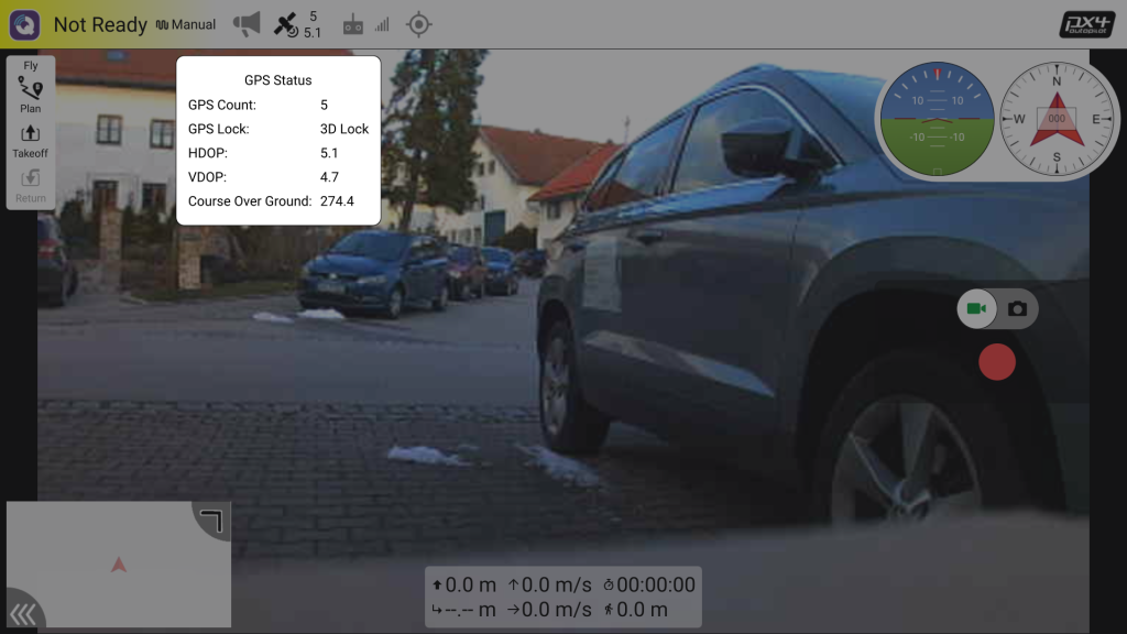
On my Android phone everything works A OK. I have a video stream on VLC and also in the QGC app, which can be downloaded for Android from the Google Play Store. There you can also find the Auterion Mission Control, which is the professional version of the QGC to work with the Auterion Skynode, the professional and much more advanced version of the Pixhawk. I had the pleasure of working with both briefly during my last project and there is only one word to describe the experience: Awesome. Hardware, Firmware, Application, Documentation, Customer Support… A full package that leaves no obstacles when integrating it to professional grade unmanned vehicles and all based on… PX4. But we are deviating again.
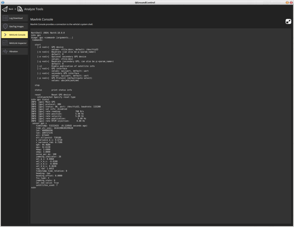
So with the FMU, Wifi, GPS and battery put back together again and exposed to fresh air, we have the video and data on our Android app and even get a 3D position fix. A little fun fact here: With the SimToo firmware the serial connection to the GPS was running on 38.400bps, whereas the PX4 firmware manages to work with 115.200 and again out of the box. No new driver needed, and nothing else to configure than adding “gps” to the driver section in the default.cmake file. Another fun fact: When watching the video stream on VLC, it is a bit laggy (about 1-2 seconds independantly on my PC and on my phone) whereas watching in the QGC app it is much more responsive and with almost no lag at all. Same thing applies to the data coming from the IMU – the artificial horizon is reacting instantly on every move. Only the magnetic compass is drifting quite a bit, but this is most probably a matter of calibration and settings.
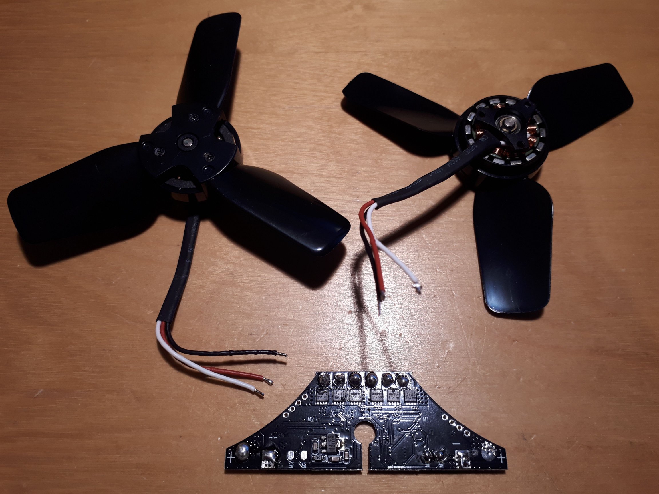
A new set of ESCs nicely packed into a drone
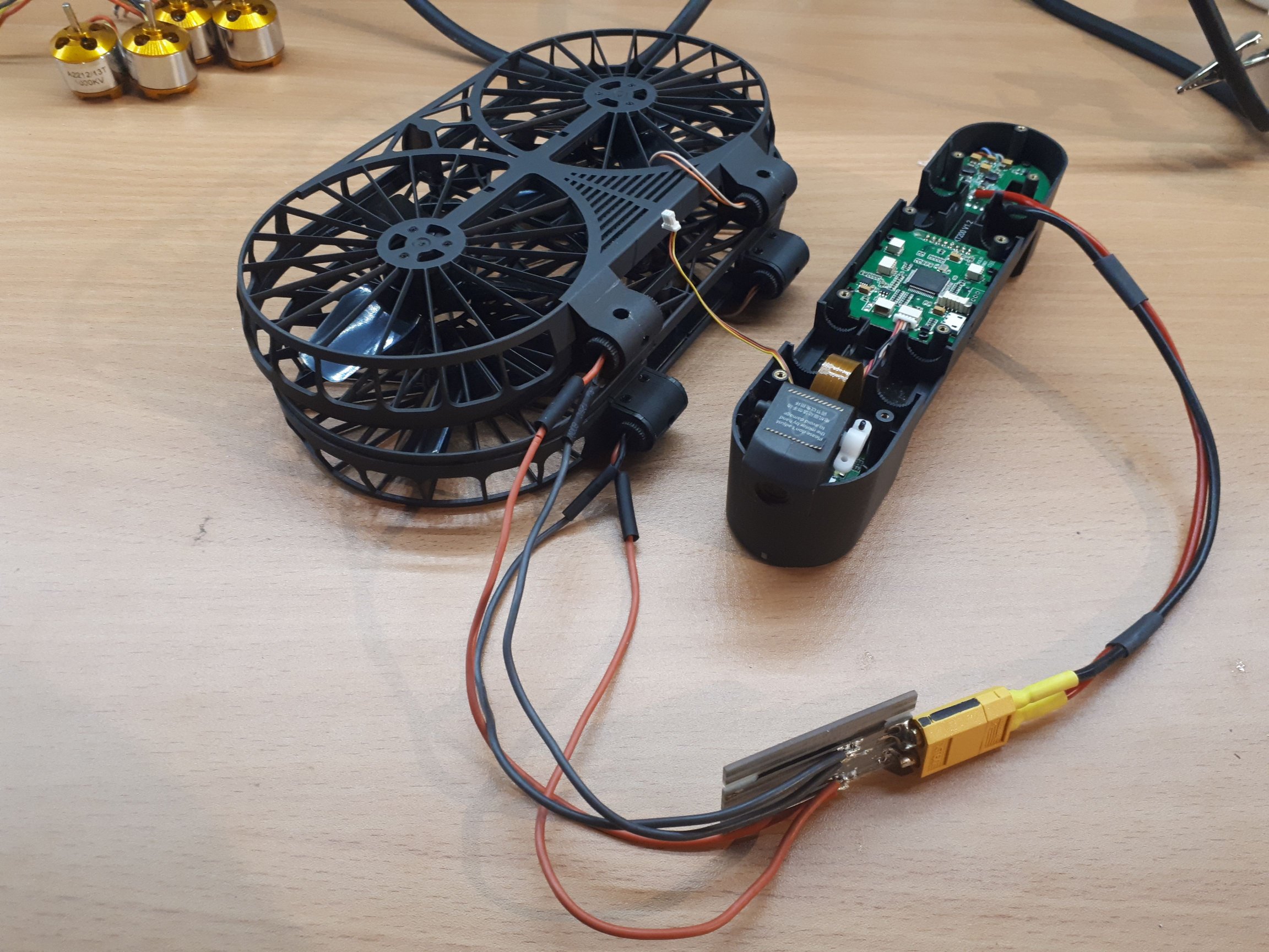
In the mean time I have received the new drone and already started taking out the ESCs and prepare the measuring of the PWM so we can add the limits to our PX4-Autopilot.
Outsourcing the fans for better data collection
Another interesting aspect will be the battery, which seems to be somewhat smart. At least smart enough to provide its charging status via I2C, since neither the FMU nor the power distribution board seems to have any means of measuring power or capacity but it is shown on the UI of the App.
How I ended up reverse-engineering (yet another) quadrocopter and replacing the proprietary firmware with open source to turn a product well meant into a package well done
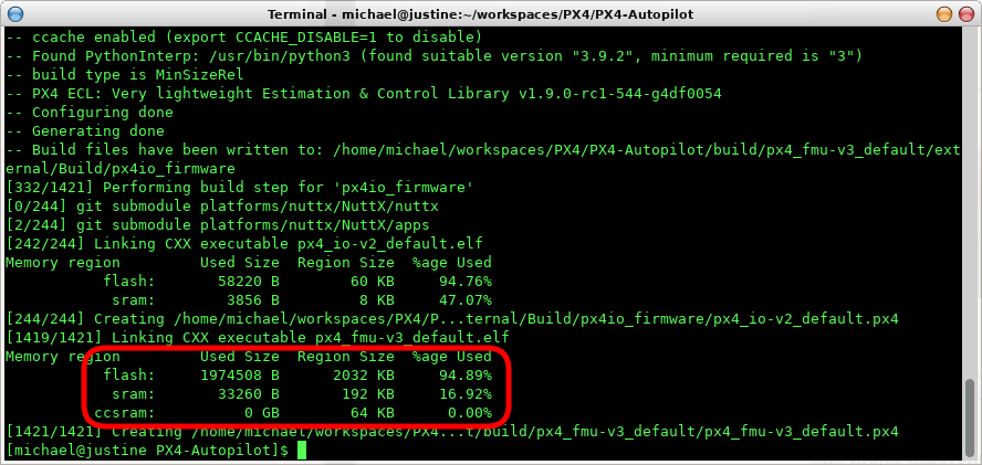
One major difference between the Pixhawk FMU_V3 I had im my drawer and the SimToo Moment Hoshi 007PRO Airselfie Drone FMU is not only the package (the latter came with a full drone around it), but also the core. The Pixhawk is running on a STM32F427 and even has an IO board (more on that later), while the SimToo only has a STMF32F405 inside. They may run equally fast, but the memory on the F405 is only half the size of what the F427 has. (Apparently there has been a hardware bug on the earlier versions of the F427, limiting the usable flash memory to 1MB as on the F405, but luckily my board has the newer, not-affected revision of the MCU on it).
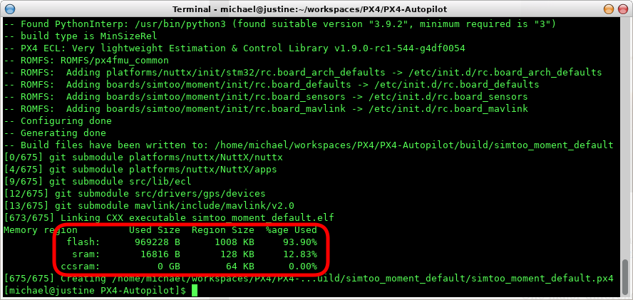
When building the px4_fmu_v3 firmware, it shows that the resulting binary will occupy almost the full 2MB of flash, whereas our simtoo_moment firmware only takes almost 1MB, which is still more than 90% of what we have on the MCU due to the smaller capacity.
There is a few places where we can tweak the amount of logic that is supposed to go into the autopilot. One of them is the file PX4-Autopilot/boards/<make>/<type>/default.cmake. It contains a list of drivers and modules that shall be used in the autopilot.
PX4_FMU_V3
SimToo Moment
DRIVERS
DRIVERS
adc/board_adc
imu/invensense/mpu6500
adc/ads1115
# barometer/bmp280
barometer # all available barometer drivers
magnetometer/hmc5883
batt_smbus
gps
camera_capture
#optical_flow/pmw3901
camera_trigger
#distance_sensor/vl53l1x
differential_pressure # all available differential pressure drivers
#pwm_out
distance_sensor # all available distance sensor drivers
dshot
gps
#heater
#imu # all available imu drivers
imu/analog_devices/adis16448
imu/l3gd20
imu/lsm303d
imu/invensense/icm20608g
imu/invensense/icm20948
imu/invensense/mpu6000
imu/invensense/mpu9250
irlock
lights/blinkm
lights/rgbled
lights/rgbled_ncp5623c
magnetometer # all available magnetometer drivers
#optical_flow # all available optical flow drivers
optical_flow/px4flow
#osd
pca9685
pca9685_pwm_out
#power_monitor/ina226
#protocol_splitter
pwm_input
pwm_out_sim
pwm_out
px4io
roboclaw
telemetry # all available telemetry drivers
test_ppm
tone_alarm
uavcan
Comparison of the Drivers
Another awesome feature of the PX4-Autopilot is its versatility. The default configurations can run on a few different boards with as many different sensors. But this comes with the price that you have to carry the drivers for all of the sensors with you. All the time. As you can see in the table above, the full package of all available drivers for differential pressure sensors, distance sensors and 7 IMU drivers are being linked into the firmware for the FMU-V3. Commenting out some of the drivers reduced the size of the binary already by 10% and quite likely a similar effect can be seen when reviewing the modules. So we might have some space to optimize our firmware package to perfectly fit the hardware it is running on.
A comprehensive description of the “Modules & Commands” can be found in the PX4 Documentation. My personal favorite passage was this one:
I mean, how smart (or lazy) is that? Writing your code well enough that it is not only fit to fly, drive, steer, control your autonomous system, but also provides a full blown auto generated documentation. A feature most of the (self proclaimed) professional manufacturers would rather neglect or even prohibit to minimize time and cost during development. If only they took into account that the time spent on well documented products will most likely save even more time and resources in a later part of the products’ lifecycle, leave alone the headaches for the developers when looking at code only ten days away from writing it, especially when working in a team. But where were we…? Ah, yes, memory.
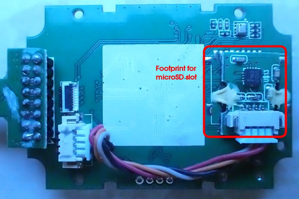
The first time I was using a Pixhawk, I got a little annoyed that I had to calibrate the IMU and magnetometer after each restart over and over again. As it turned out this was not a flaw of the board or the firmware, but only my very own fault: All I had to do was to add a microSD card to the board and it was able to store the data all along. But the SimToo FMU doesn’t have any slots for external memory… Well, there seems to be some footprint for a slot on the back side, but it isn’t populated and instead has the magnetic compass glued to it.
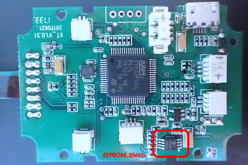
The Flash to the rescue. We haven’t used the full potential of the SimToo FMU, yet – as we saw in the closer look at the hardware, it comes with a 256Kb flash memory, which actually is 32KB because the Kb is referring to the zeroes and ones instead of the bytes like on every other memory storage device and I will never understand why the manufacturerers of flash memories are doing this. It is one of the rare occasions where the French do have an advantage in their habbit of naming everything differently from the rest of the world – computers are being called ordinateurs, a mouse is a souris and they are calling a byte an octet, which is actually pretty precise and prevents confusion when it comes to Kb and KB.
So as suggested in the reply by Lorenz Meier to a post about “Porting px4 to system without sd card” (I do admire how the creator of the PX4 environment took his time to reply to those posts himself and he still does on Slack and various other platforms. I mean: does he ever sleep??), we are going to use the flash chip as the storage for the calibration data. Even more, since the chip has a capacity of 32KB, we might as well store some other data on it. The driver for the Microchip 24xx256 EEPROM on our board is already part of the package, so all we have to do is add some configuration:
“The primary governing standards” of NuttX being “POSIX and ANSI” and including “standard APIs from Unix“, it is no surprise that internally the EEPROM is being utilized as a file system, which can even be accessed in the nsh console just like on any other Unix system. What we are doing in our configuration is once again putting together a best-of from other boards: We create four partitions where the first two will be holding parameters and waypoints (more on that later), the third will contain the calibration data and the last will contain some ID, which I yet have to find out more about. It is worth noting that the space allocated for the partitions consists of blocks each 32 bytes wide, so in total we are using only 10KB of the 32 and save the remaining space maybe for something else later.
It was already tempting to get hands on the original firmware binaries, which I stepped away from in favor of progressing with this project. I did however read out the original content of the EEPROM by adding a few lines to the first firmware we were trying on the board, based on the STM32 HAL. But the result was rather not so interesting as the flash chip did not contain any interesting information.
main.c
// should be on top, put here for demonstration purpose only
#define EEPROM_MEMORY_SIZE 256 * 1024 / 8

  // ref. DS20001203 Revision W "256K I2C Serial EEPROM", chapter 5.0 "Device Addressing"
  uint16_t _device_address = 0x0a << 4;

  uint16_t _memory_address = 0;

  uint16_t _read_size = EEPROM_MEMORY_SIZE;

  uint8_t _data[_read_size];
  memset (&_data, 0, _read_size);

  HAL_StatusTypeDef _status = HAL_OK;

  _status = HAL_I2C_Mem_Read(&hi2c2, _device_address, _memory_address, I2C_MEMADD_SIZE_16BIT, _data, _read_size, 1000);

  HAL_UART_Transmit(&huart2, _data, _read_size, 1000);

  HAL_Delay(1000);
Now we know more about the drivers and modules in general and are able to store the calibration and other data on the flash memory. Next time we will try to run the board on the battery only, connect the GPS and use the camera.
How I ended up reverse-engineering (yet another) quadrocopter and replacing the proprietary firmware with open source to turn a product well meant into a package well done
Up to now we had a closer look at the hardware of our SimToo Moment Hoshi 007PRO Airselfie Drone, created a bootloader and a basic firmware, which we flashed via the QGroundControl application. This time we will be dealing with communication.
As we have seen before, the QGC is already talking to our board via USB out of the box. The protocol involved is called “Micro Air Vehicle Link” or just MAVLink, the defacto standard for communication between Ground Control Stations and Unmanned vehicles and guess where it has been born and raised… Right, it’s another offspring of the PX4 environment.
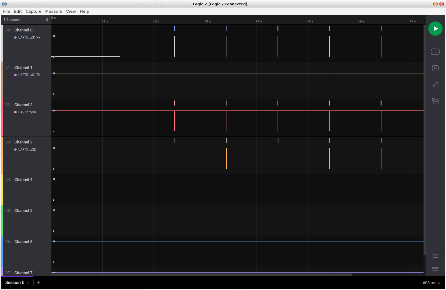
Poking U(S)ARTs
While poking around with my logic analyzer on the various interfaces connected to the flight management unit (FMU), I found five serial interfaces. Two SPIs that are used for the IMU and the baro sensor and three U(S)ART interfaces:
USART2 connected to the Optical Flow Sensor, running at 115.200 bps
UART5 connected to the WiFi module, running at 115.200 bps
USART6 connected to the GPS, running at 38.400 bps
Two sensors and one radio narrows our desired channel of communication down quite a lot.
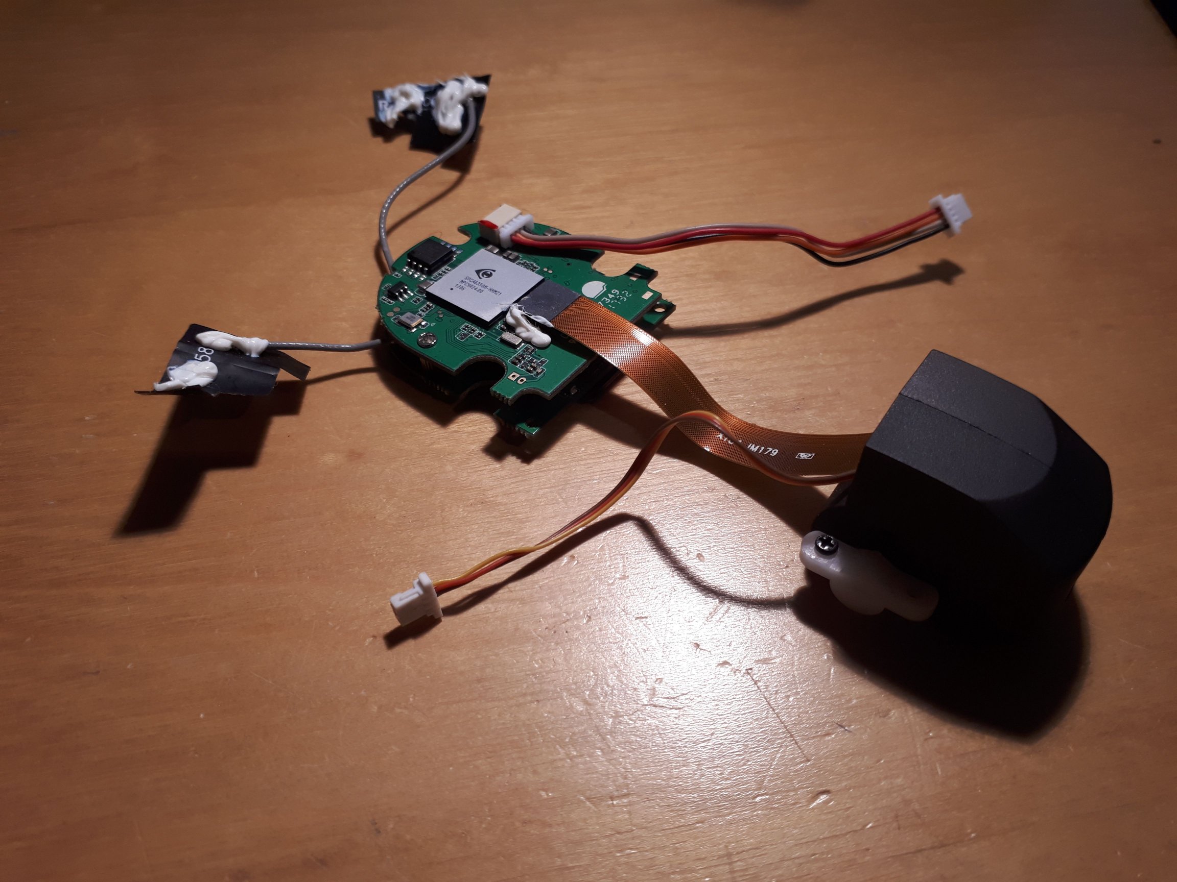
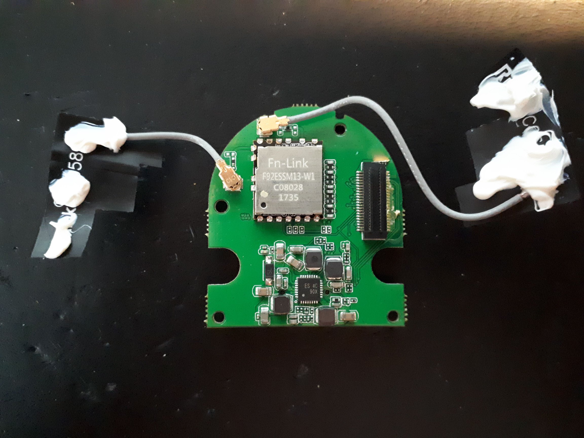
The WiFi module is a stacked PCB with antennas, a camera and has a microSD slot. Two cables are running from the FMU to the unit, one with the 5VDC power / GND and the RX and TX of UART5, the other is connected to the tilt servo of the camera.
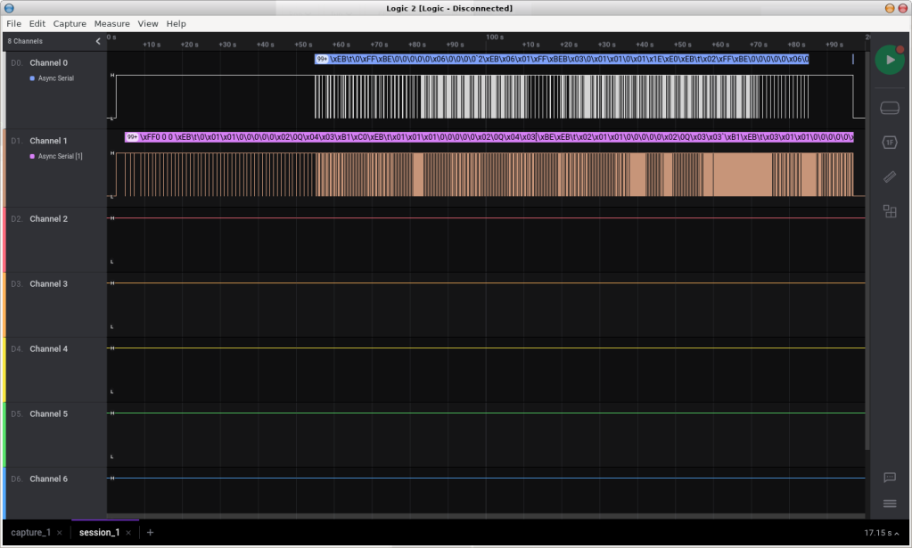
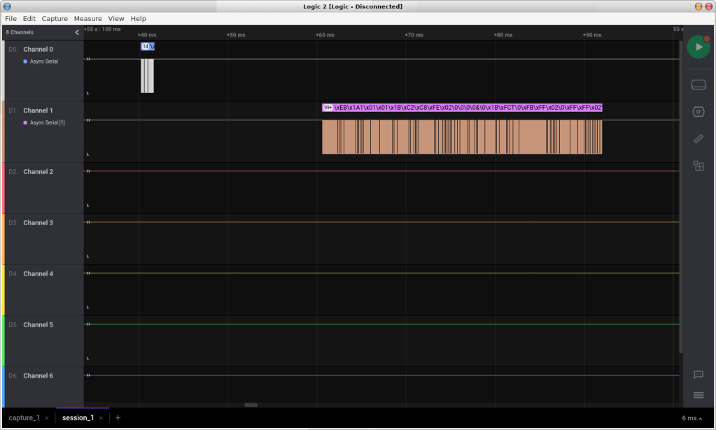
There was a lot of data going back and forth on the serial port between the FMU and the module, starting when pairing with my phone and increasing when connecting the app but that was only half of the story. When I saw e.g. that triggering camera shots put a significant delay of messages to the stream, I also wanted to see what was going on in the air between my phone and the drone.
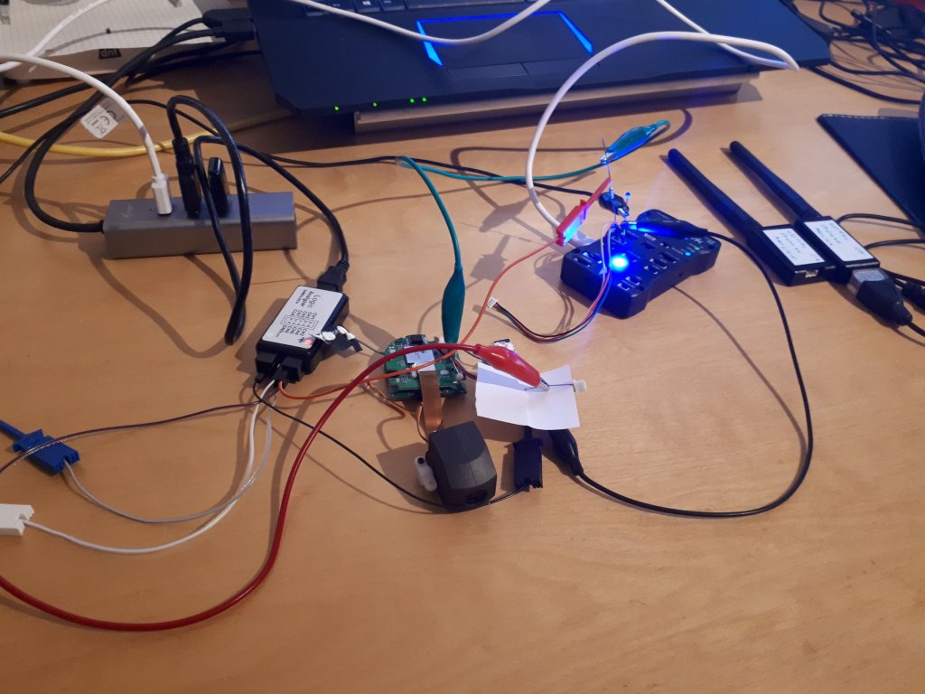
My first idea was just joining the network with my computer and recording the communication with wireshark, but that would’ve been just too easy. The WiFi Access Point does only accept one connection at a time and so it was either my phone or my PC. There was no app for the latter, so there also was no communication to spy on without the phone involved. Running wireshark on Android would certainly have been an option, but I wanted to keep the workload on it low and also have the serial data in parallel. So I went for a man-in-the-middle attack. First with a Raspberry Pi until I figured the communication chain from my PC to the house WiFi then to the RPi which had a second WiFi connected to act as an accesspoint for my phone and a bridge to the drone… you probably can see the total overkill here and the many levels that didn’t really compensate for the lags they were creating.
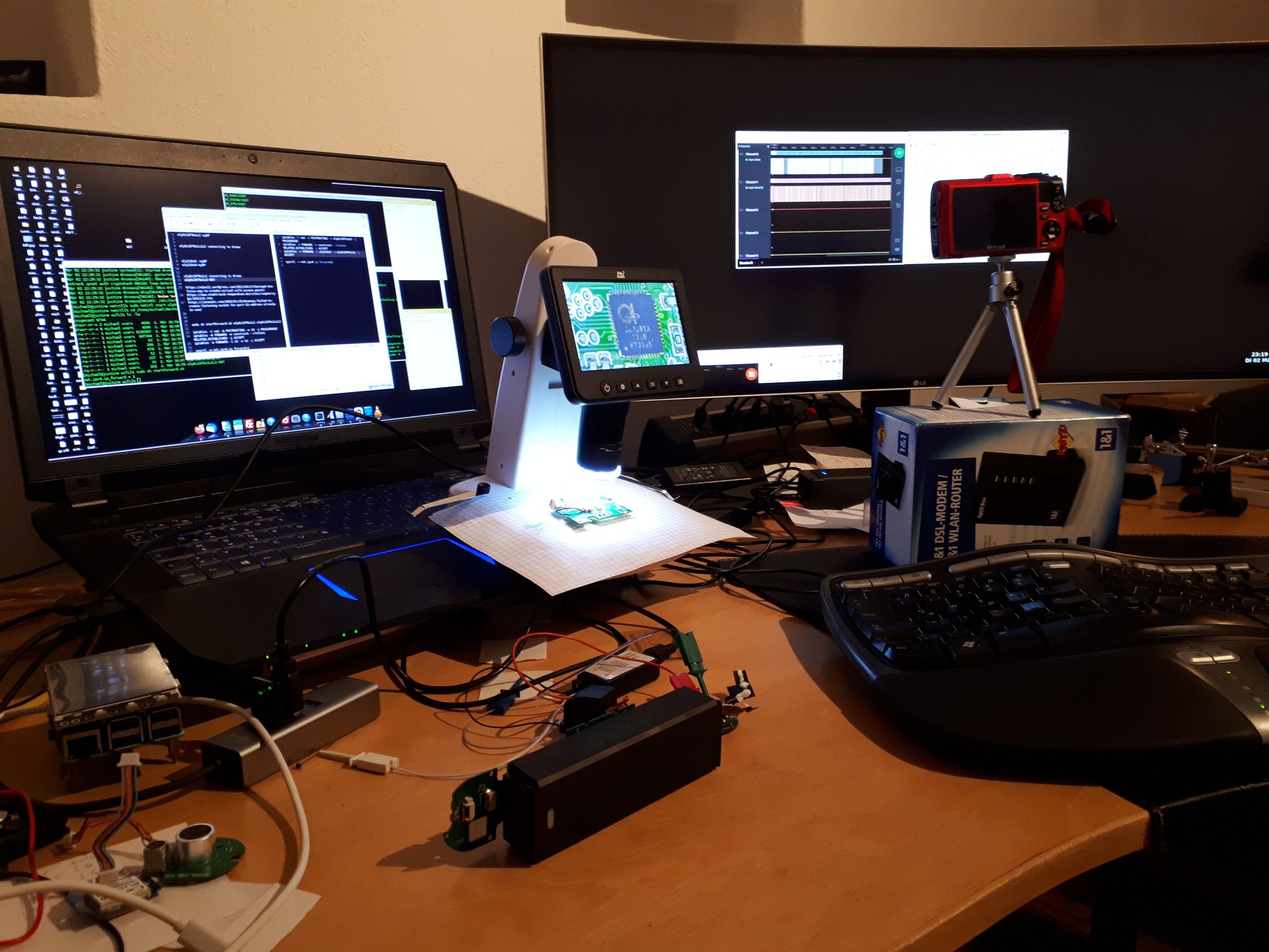
Long story short, the final setup consisted of a WiFi dongle connected to my PC, (actually it was two, since I didn’t want to give up on the connection to the internet via the internal WiFi), while acting as a AP to my phone and at the same time connecting to the drone. In between my computer was running wireshark to record the network communication and the logic analyzer to record the serial communication. The scenery was finally filmed by a camera (which by way also has a WiFi AP and I always was wondering… focus, Michael, focus.). The video was to keep the effort low for synchronizing the two other recordings, as I could see the timestamps of wireshark and the UA(S)ARTs later on the video. And here is what I found:
Phone 192.168.1.10
Drone 192.168.1.1
Observation
various
8080
Drone to App
various
8888
App to Drone
various
15740
Taking Pictures
RTSP
554
Streaming Video
FTP
21
Access to the storage
Findings in the network streams between the Phone and the Drone
Disecting the recorded data would be filling a whole other story, but there is already a lot about this topic out there. SimToo didn’t reinvent the wheel here, maybe not even develop the WiFi AP / camera combo themselves. Instead the module is following the ISO 15740 (hence the port), also known as the Picture Transfer Protocol (PTP), which was created “to allow the transfer of images from digital cameras to computers and other peripheral devices without the need of additional device drivers.” Additionally, it offers a live video stream on Port 554, the standard port for the Real Time Streaming Protocol and it has a FTP server running to directly access the data storage. This one I found just by chance, because the app isn’t even using this option, but relying totally on the PTP. Meaning, the whole handling of the payload aka camera is happening without involvement of the FMU – but then how does the app talk to the Autopilot?
Well, the ports 8080 and 8888 seem to be directly “connected” to the UART, i.e. sending any data to port 8080 will result as the very same data being transmitted at 115.200 bps to the FMU and vice versa, data from the FMU is being sent out on port 8888 (which btw. can easily be tested on Linux using Netcat). Now this is simple, isn’t it? And a perfect match for our project.
Connecting the WiFi to TELEM1 of the Pixhawk
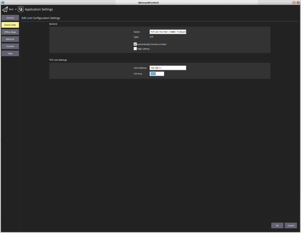
With the Pixhawk I had in my drawer also came a 433MHz Radio Telemtry Kit where one part is being connected via USB to the Ground Station and the other via UART to the Pixhawk. Once hooked up, the Autopilot would start communicating with QGC without the USB cable connected, again out of the box and just like this. So I started permutating the combination of Pixhawk, telemetry kit, the px4_fmu_v3 firmware, our own firmware, the WiFi AP and the SimToo FMU, learning about the Serial Port Configuration of PX4, how to set the baud rate for the MAVLink connection and just how easy it is to setup a new communication channel between a drone and QGC.
In this particular case, I had to configure just a little something on the QGC to set the ports different from the standard being 5760, but the means were already there and this is again just wonderful.
With another piece of the puzzle solved and the delivery of the second drone drawing nearer, there is only a few things left to figure out before we can reassemble the machine and go flying…
How I ended up reverse-engineering (yet another) quadrocopter and replacing the proprietary firmware with open source to turn a product well meant into a package well done
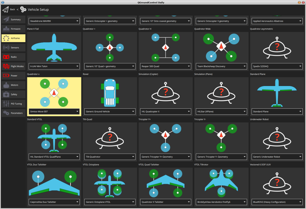
Equipped with plenty of knowledge about the hardware and a bootloader to start with, we can now concentrate on the main task: Configuring the PX4-Autopilot to work with the SimToo Moment Hoshi 007PRO Airselfie Drone. Just like with the bootloader we won’t need to start from a blank page, but follow the PX4 User Guide on adding a new airframe and use the configuration of the Bitcraze Crazyflie, because it is running on the same MCU.
First step was to copy the crazyflie folder and rename the flies to moves. Second step was to adjust the pin mappings in the board.h to match the setup of the FMU, namely the on-board crytsal that runs at 24MHz on the SimToo instead of 8MHz on the Crazyflie, but with the rest of the settings to keep 168MHz on the sysclock, so we can leave the peripheral clocks at the same speed. And the pins for the interfaces like I2C, SPI and UART/USART, where there were alternative options.
The corresponding settings can be found well documented in the pinmap headers of NuttX (another great choice of PX4 as the RTOS), so for our STM32F405 it would be the under PX4-Autopilot/platforms/nuttx/Nuttx/nuttx/arch/arm/src/stm32/hardware/stm32f40xxx_pinmap.h. I would never have found this without the extensive code search capabilities of Eclipse. Even though I started liking Atom as “a hackable text editor for the 21st Century” and my new goto-IDE for python, but the code search on Eclipse.. just priceless, not to mention the STM32 related tools that come with the CubeIDE flavor. But lets focus.
For the DMA I haven’t decided, yet, which one to use, since the UART5_TX and I2C_TX seem to be conflicting, so I just configured them only for the UART/USART RX channels.
More configurations / options need to be setup in the rc.board_<section> files, where “section” refers to “defaults”, “mavlink”, “sensors” and maybe others, that haven’t been used for the crazyflie setup. Here we need to define board specific parameters, the mavlink channel (e.g. USB or UART) and the sensors to be used, but peeking was allowed and the setups for the other boards along with the search function of Eclipse were quite helpful.
#!/bin/sh
#
# boar specific sensors init
#------------------------------------------------------------------------------

# todo: check applicable for simtoo moment
#board_adc start

# IMU
mpu6500 -s -R 0 start
# Compass
hmc5883 -T -I -R 0 start
# Baro not known, yet
#bmp280 -s start
So far I only added the IMU and Compass, for the Baro I need to find the right driver, first. Or maybe even implement it.
Another important configuration file is the <board_folder>/nuttx-config/nsh/defconfigfile. It is not supposed to be edited manually, but with the kernel configuration tool being called by make <boardname> menuconfig, but here I allowed myself to deviate from the path. There might be some space for improvement, though, since I tried to condense what I found in the other board configurations, above all the FMU_v2, which is working well with the Pixhawk I initially intended to use. But most important for now were again the configurations for the interfaces and disabling the ones not present, like the SDIO / MMC to avoid any mismatches.
Then there is the board_init.c, which seems to be the entry point for the autopilot when it comes to (oh wonder) initialize the board specific interfaces and also the individual interface files like board_i2c, board_spi and board_usb. The UART/USART don’t seem to need a specific init file, as they are covered by the corresponding peripherals like the GPS, Mavlink and such.
Almost done, but the airframe parameters still need to be set in the PX4-Autopilot/ROMFS/px4fmu_common/init.d/airframes/<id>_<name> file. As ID I chose 4902, which needs to be checked for validity and the parameters are again mostly derived from other configurations and what I found in the documentation. This will also be the place for limiting the PWM settings, once I have retrieved them from the second drone in action.
The above ID and name have to be added to the CMakeLists.txt, too.
And that’s it. With these basic settings we are ready to build our first iteration of the new autopilot software and flash it.
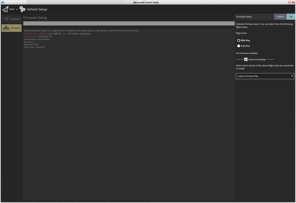
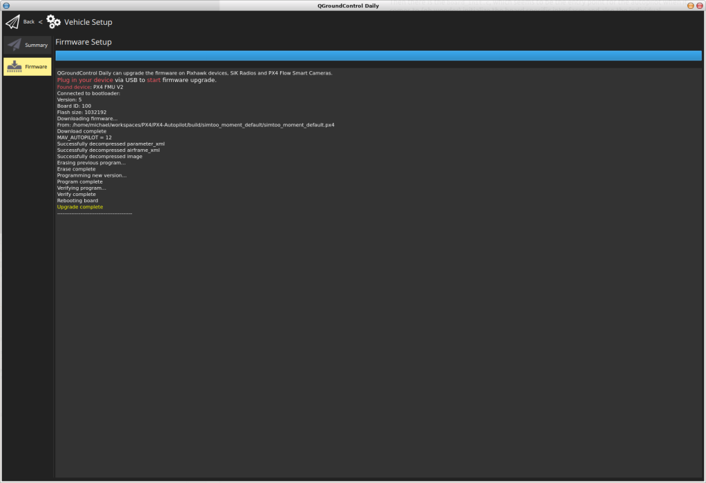
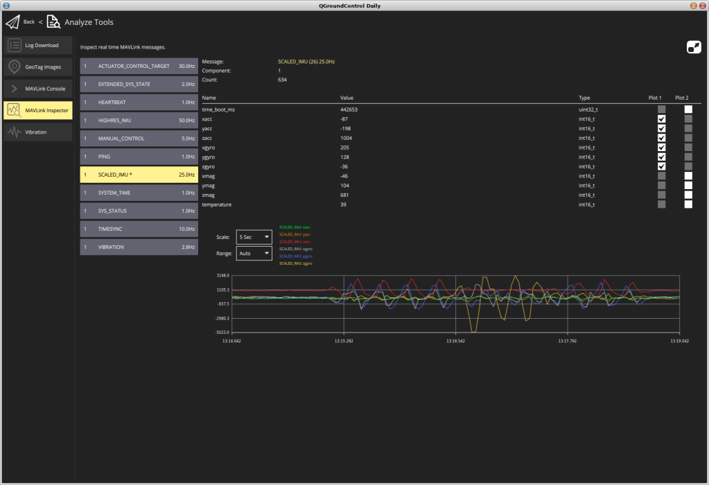
Since this part of the project has been rather dry and without much play, how about we reward ourselves with another master piece of the PX4 environment: QGroundControl, the Ground Control Station based on QT, often copied (even from scratch… I mean… duh??), but never reached and amongst many other things also a wonderful tool for uploading the new firmware. Yes, you read it alright: Now that we have a bootloader on board, we can either let make <boardname> upload do the work or just use make <boardname> to create the binary and point QGC to the result. The second approach has the advantage that the .px4 file of the firmware contains some meta-info about the new airframe, which will go into the configuration menus of QGC. Another plus is the ability to test and interface the ground control application with the autopilot, get some live data and even… but first things first:
You can either download a pre-built binary of QGC, which is available for multiple different platforms, including Android (and there’s the spoiler for “how are we going to replace the fancy SimToo App?”), or you can build the application yourself. Of course, I chose the latter, at least for my Linux work horse.
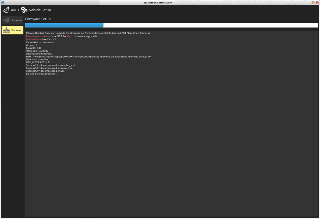
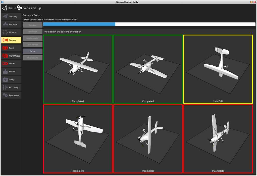
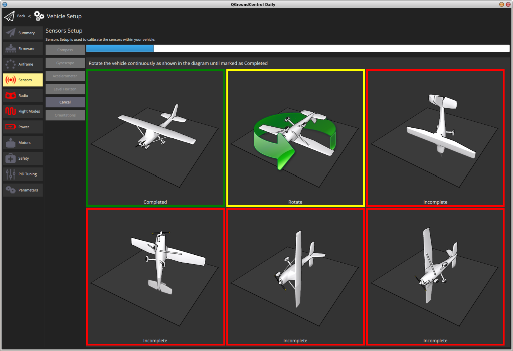
Once the Application is built / installed, just start it with the autopilot disconnected. Then open the vehicle setup menu and chose “Firmware”. Now is the time to connect the autopilot via USB to the computer. The bootloader will kick in and tell QGC that it is ready to receive new firmware. Chose “Custom firmware file…” in the drop down list on the right, click “OK” and navigate to the .px4 file in the build-folder of your PX4-Autopilot. The upload will start automagically and so should the reboot of the board. I had to disconnect / reconnect my board, though, but then, after the bootloader has timed-out waiting for new firmware and jumped to the autopilot instead, it also started communicating with the ground station. Just like this. Via USB for now, but still, it is alive!
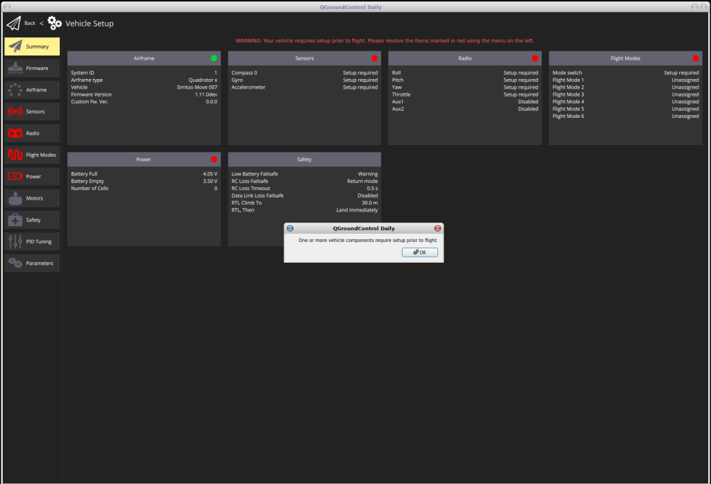
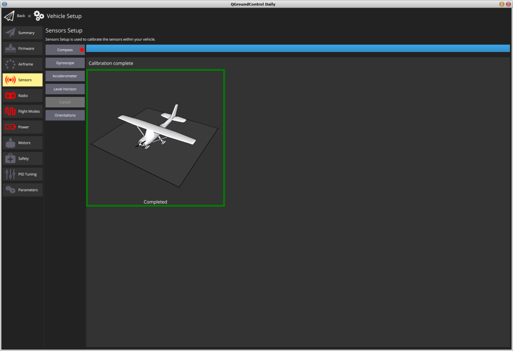
QGC is asking us to setup “one or more vehicle components” prior to flight, which we will gladly do and by that see the sensors working just fine.
Connected
This is it, a small step for configuration, but a big step closer to the big goal of flying the SimToo Moment Hoshi 007PRO Airselfie Drone with PX4 on board.
The simtoo_moment branch of the PX4-Autopilot can be found in my github repository.
The next steps will be a verification of the parameters, modules and missing drivers, getting the GPS to work, find or write the driver for the Baro, connect to the wifi and camera (wait until you see what I have found there…), check the limits for the PWM and once all is set and ready: Go flying. If the days only had more hours…
How I ended up reverse-engineering (yet another) quadrocopter and replacing the proprietary firmware with open source to turn a product well meant into a package well done
Now that we know the hardware of the SimToo Moment Hoshi 007PRO Airselfie Drone and have full access to it, it is time to get serious and put it to a good use. If only we had the resources and the wisdom to create some software that could later be used “in a wide range of use-cases, from consumer drones to industrial applications”* and maybe become “the leading research platform for drones”* and be “successfully applied to under water vehicles and boats”* or even be the flight controller on the jetmans back pack (may he rest in peace).
And open source… It should definitely be available to everyone to use and contribute to. A world wide project incorporating the best-offs from multiple disciplines. And also have a ground control software for it, versatile and running on multiple platforms. And support. A dedicated team of experts helping with the integration and development into commercial applications, creating awesome success stories. Wait… isn’t that exactly what PX4 is? (*above quotes were taken from their web-site).
It is in deed amazing what has become of the project that Lorenz Meier and his team at the ETH Zurich created in 2008. There is no doubt it will also be working on our drone, too and here’s how we are going to achieve this:
Those who entered the world of microcontrollers via Arduino might be well familiar with the concept of having a bootloader. Like every sane project (or lazy in terms of “using the programmer only once and from then on just the USB-Port for uploading new firmware and at the same time having a console to access the main frame”), PX4 comes with one.
The good thing (amongst many others) about open source projects is that you don’t have to re-invent the wheel. As I mentioned before, there are already platforms based on the STM32F405 using PX4, namely the bitcraze Crazyflie and so of course there is a section in the hw_config.h of the PX4-Bootloader for it. So as suggested in the (again awesome) User Guide under the chapter “Adding a New Airframe Configuration“, we just copy the existing configuration and adjust the parameters to fit our own drone, which is yet another very smart move of the project: You can redefine the software by changing parameters without touching the core.
I did touch the core though, since the SimToo FMU is not exactly following the Hardware Reference Design and missing the status LEDs. So I introduced a define for “NO_LEDS”, turning the calls for blinking into empty ones in the main_f4.c.
Once the parameters are set and the Makefile prepared, simply call “make”, flash the bootloader, disconnect the programmer, connect the USB Cable, do a lsusb and enjoy the beautiful sight of a brand new USB device attached to your computer.
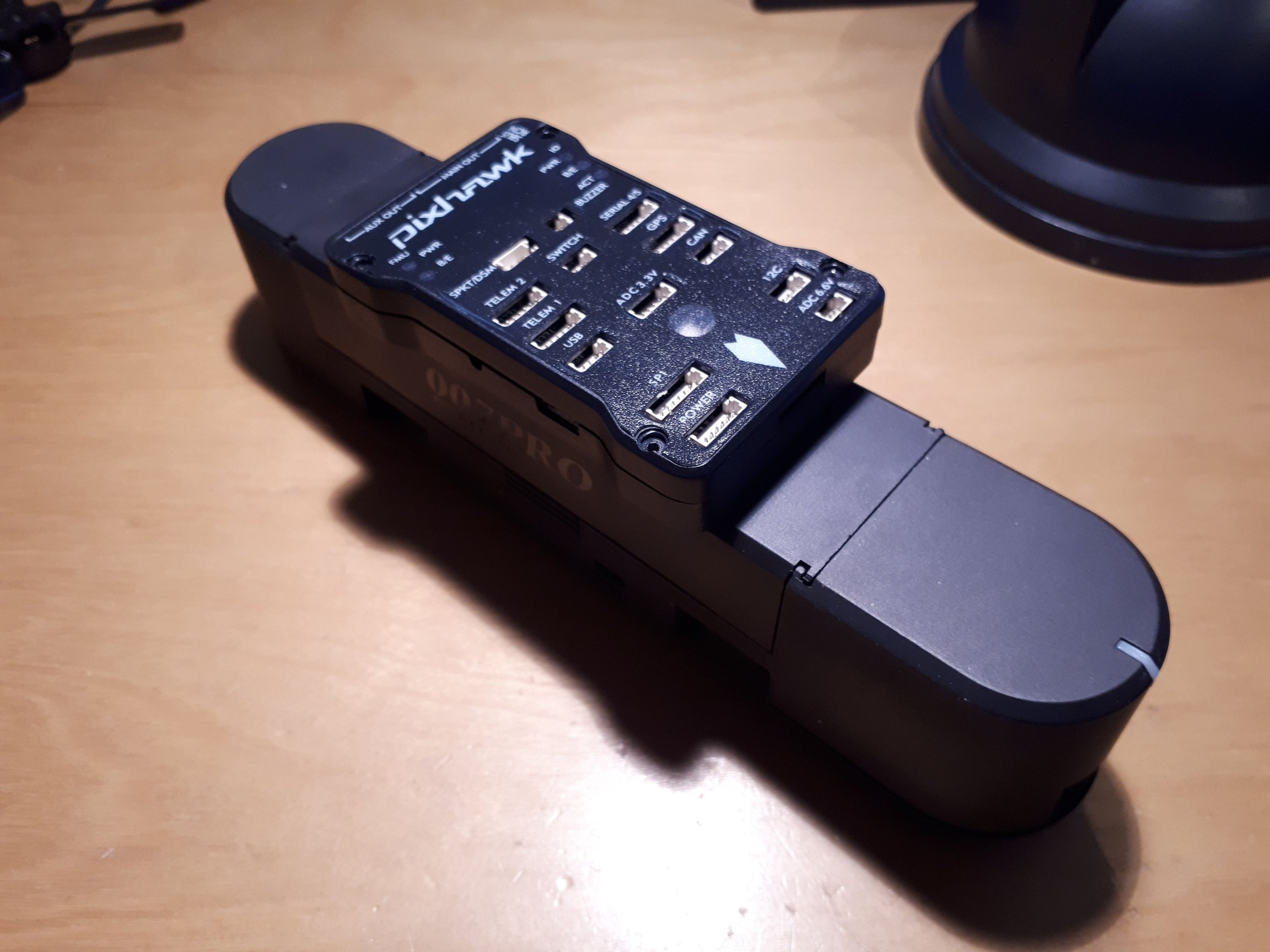
How I ended up reverse-engineering (yet another) quadrocopter and replacing the proprietary firmware with open source to turn a product well meant into a package well done
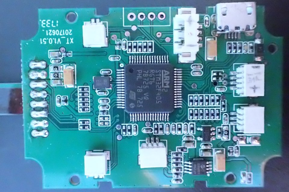
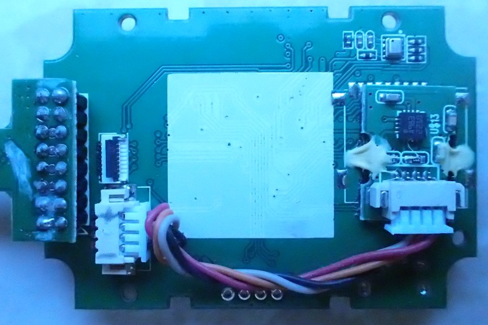
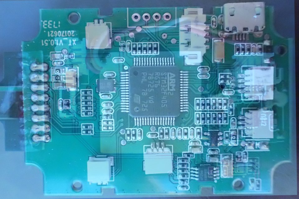
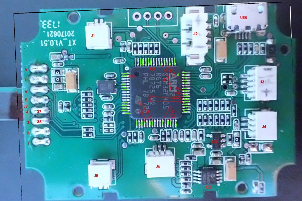
My first euphoric encounter with the SimToo Moment Hoshi 007PRO Airselfie Drone revealed that it was not only nice and shiny from the outside, but also came with some inner values. They made me more than curious so I had a closer look with my brand new digital microscope (awesome present, thanks mom and dad!), stitching and blending pictures of the PCBs’ back and front in and out, poking needles into the connectors, hooking them up to a logic analyzer and not to forget the good old beeping thingie to find endpoints of traces.
The design appears to be pretty straight forward. The PCBs seemingly have no more than four layers and are without hidden vias, populated with mainstream and well documented MCUs (or their clones) and well known sensors (or their clones). This made the reverse-engineering a rather recreative walk on a sunday afternoon.
Pinout of the STM32F405 on the FMU
The traces to and from the MCU and peripherals were easy to track down, above table can be found in my github repository.
One idle Sunday afternoon later (actually it was rather night when everybody was asleep), the system architecture looked like this to me:
Interfaces on the FMUOverall System Architecture
Adding the things I found with the logic analyzer got me this:
Interface
Peripheral
Power Lane
I2C2
Battery
7V6
I2C2
Flash Memory (4F256I)
3V3
I2C2
GPS (Beitian BN-220Q)
5VDC_2
I2C2
Magnetic Compass (A983)
3V3
PWM
Motor 1-4
7V6
PWM
Tilt Servo Camera
5VDC_1
PWM
Servo Connector, not connected
5VDC_2
SPI1
IMU (MPU6500)
3V3
SPI2
Barometric Sensor (745 311?)
3V3
SWD
Debug
3V3
USART2
Optical Flow, 115.200 bps
5VDC_2
UART5
WiFi AP, 115.200 bps
5VDC_2
USART6
GPS (Beitian BN-220Q), 38.400 bps
5VDC_2
USB
USB, CDC / VBus
5VDC_2
VDD_IN
DC/DC Converter
5VDC_2
VDD_OUT
DC/DC Converter
3V3
Interface Centric View
All in all, not many surprises here, except two things:
Why did they bother to give the tilt servo of the camera its own 5VDC power lane, which is also not connected to the USB VBus, while the second similar looking connector was on the same power lane as everything else?
What Barometric Pressure Sensor did they use? It does look like a mirrored version of the commonly used BMP280
I briefly played with the idea to go around the read protection and dump the firmware of the STM32, which would’ve been an interesting experience. But I already deviated quite a bit from the original project and didn’t see much use of keeping the old firmware with a much better solution at hand. Instead, I decided I had collected enough data along with logs from the logic analyzer and felt comfortable enough to put the new knowledge to a test.
A basic STM32CubeIDE Project based on the findings
Thanks to the STM32CubeIDE, setting up a basic project based on the findings was quite easy.
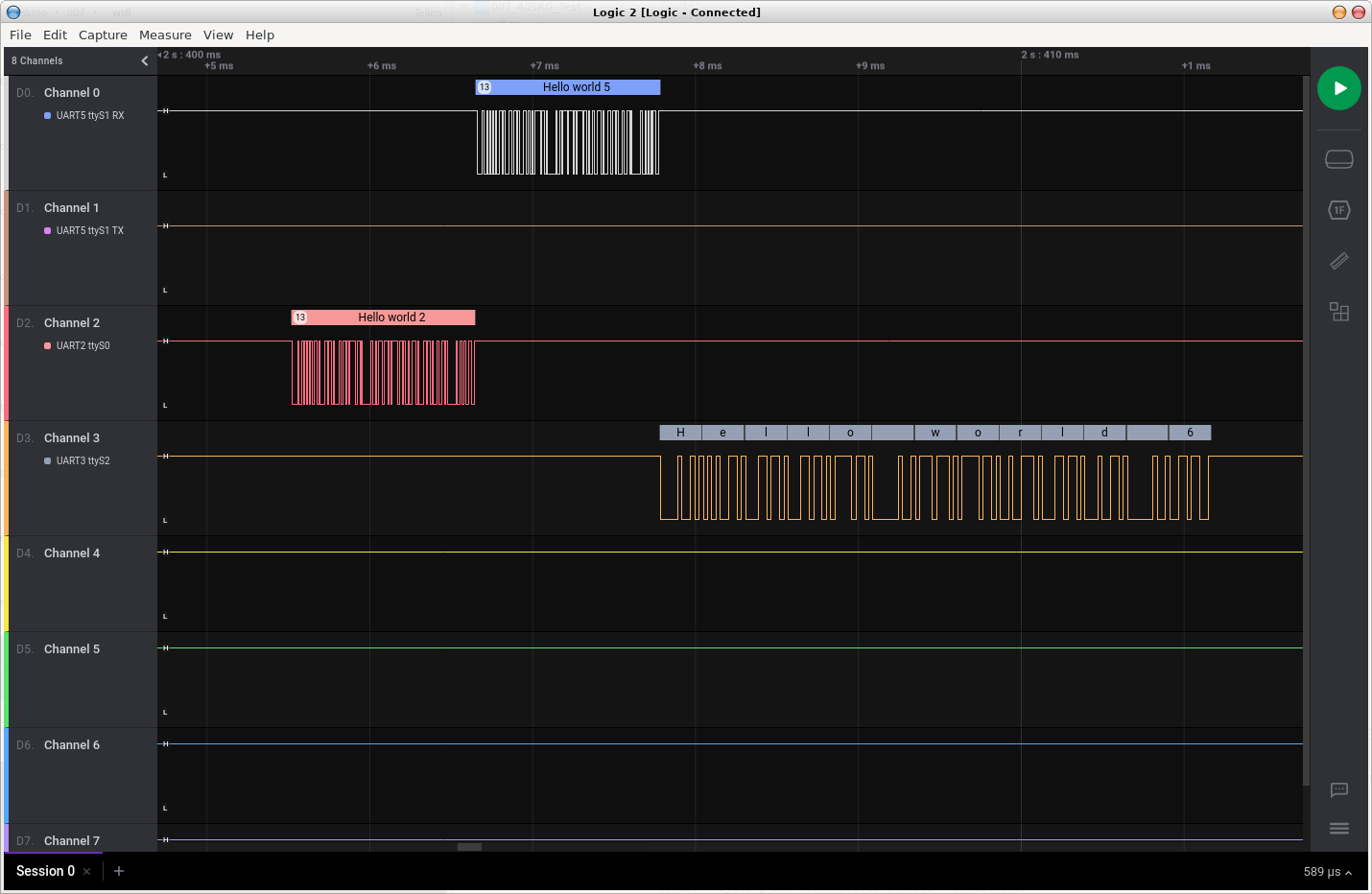
Adding just seven lines of code to send some data on the serial ports got me a working proof of concept.
/* USER CODE BEGIN WHILE */
uint8_t *_data_tx_2 = (uint8_t*)"Hello world 2";
uint8_t *_data_tx_5 = (uint8_t*)"Hello world 5";
uint8_t *_data_tx_6 = (uint8_t*)"Hello world 6";
while (1) {
    HAL_Delay(1000);
    HAL_UART_Transmit(&huart2, _data_tx_2, 13, 1000);
    HAL_UART_Transmit(&huart5, _data_tx_5, 13, 1000);
    HAL_UART_Transmit(&huart6, _data_tx_6, 13, 1000);
/* USER CODE END WHILE */
The project can be found on my github repository. Please note that the linker script has already been adjusted to work with the PX4-Bootloader, which means the start address is not at 0x08000000, but at 0x08004000. But this is going to be another chapter.
How I ended up reverse-engineering (yet another) quadrocopter and replacing the proprietary firmware with open source to turn a product well meant into a package well done
Initially I was looking for some lightweight brushless motors with propellers, preferably surrounded by a cage for adding them to a new design, when I came across the SimToo Moment Hoshi 007PRO Airselfie Drone. While most people might have seen just another quadrocopter with a camera for a decent price on one of the big gadget selling portals, for me it was a package of spare parts for less than 100 Euros – Little did I know what I was really about to find.
The box arrived within a week
Getting the drone took less than a week and I didn’t even mean to turn it on before taking it apart, but the reviews and few videos I found all suggested the handling would be so terrible that I wanted to see it myself in action. The box was surprisingly fancy, there were no cheap plastic inlays holding the content, instead the drone was packaged in a neat little shock absorbing case, holding not only the drone, but also a set of two batteries and a charger. The drone itself also felt quite well manufactured with light but seemingly stable enough cages around the propellers, smooth edges and a rubbery surface, so it wouldn’t slip out of your sweaty hands when taking it out of your backpack after a long hike to the top of a mountain.
Screenshot of the app
The app was easy to find and install, pairing the drone with my phone worked like a charm and the first flight… well, controlling a drone with a 5 inch touch screen never was the brightest idea – I mean, there is a reason why most manufacturers would provide a haptic controller either with its own display or using your smart phone as means of visualization.
The first flight went smooth, going a little up and down and turning around the z-axis, but when I was about to do some showing off in front of my wife, the little bird (the copter, not my wife) did not respond that well to the commands. Even worse, when telling it to land, it just went up and got stuck. Luckily we were inside the house, so the ascend was stopped by the ceiling and I only had to climb a chair to rescue the drone.
An ancient AR Drone
But this reminded me of what happened to a friend of mine: When he tried to inspect his roof with a first generation Parrot AR Drone, the quadcopter just started gaining altitude until it ran out of battery. Fortunately, there was no wind, so it just fell out of the skies almost at the same spot it took off a few minutes earlier.
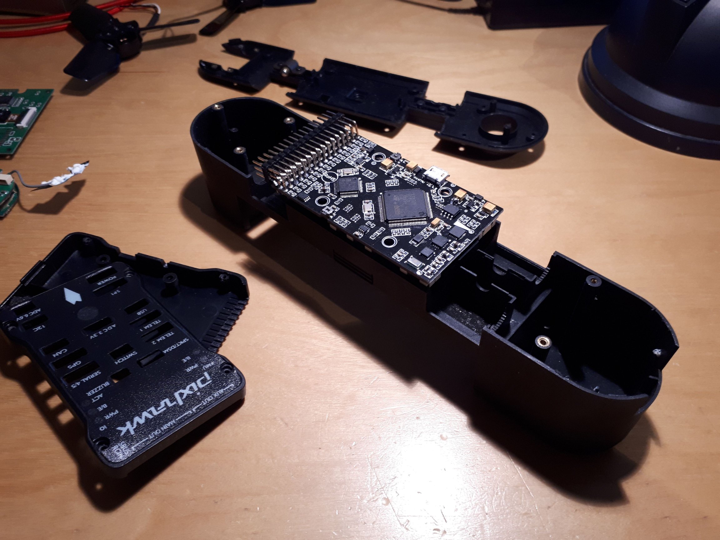
After seeing enough to confirm the comments about the not so very convincing reliability of the firmware, I started tearing down the drone, stripping it from its electronics and tried to fit an old Pixhawk I had in my drawer into the fuselage.
3D Printed Body
Unfortunately the hull was a bit too narrow, so I went for printing a new main body.
Just a few steps away from a maiden flight, it was time to test the motors with the Pixhawk. After the second ramp up, the FETs just got blown (an effect I have seen not long ago, just can’t recall where that might have been…). Apparently there is some sort of limitation to the range of input, which was not caught by the controller on the ESC and I was back to square 1, since I did not have any specs for the motors and didn’t want to burn them with an ESC other than the original.
That was not going to stop my project, but where was I supposed to find a replacement? Claiming anything from the reseller was not an option, since burning the board was obviously my own fault. Also a search for spare parts only got me empty cages without any electronics. I also tried to open a channel towards the manufacturer SimToo, but they are nowhere to be found. So the fastest and probably cheapest way to keep the motor-cage approach alive was to order another drone.
While waiting for the replacement to arrive, I took a closer look at the guts of the torn down drone. And instead of some rather pragmatic design or signs of hasty manufacturing you usually find in cheap remote controlled toys, I was again surprised by the clean and modular setup.
In fact, the drone came with all the bells and whistles of a modern and professional UAV:
Power Distribution Board (PDB) connecting to
LiIon LiPoHV Battery with 7.6V and 2900mAh
Flight Management Unit (FMU), based on a STM32F405RG
Inertial Measurement Unit (IMU) based on a Invensense MPU6500
Magnetic Compass based on A983 (either a clone or successor of the HMC5883)
Barometric Pressure Sensor (which I wasn’t able to identify, yet)
Payload consisting of a Camera with Micro-SD Slot and tilt servo
Optical Flow Sensor with GD32F103, OI-JL3281A image processor and Invensense MPU-6050 IMU
Ultra sound distance sensor with GD32F130
Along with the second battery, charger and case, a pretty nice package for less than 100,- bucks.
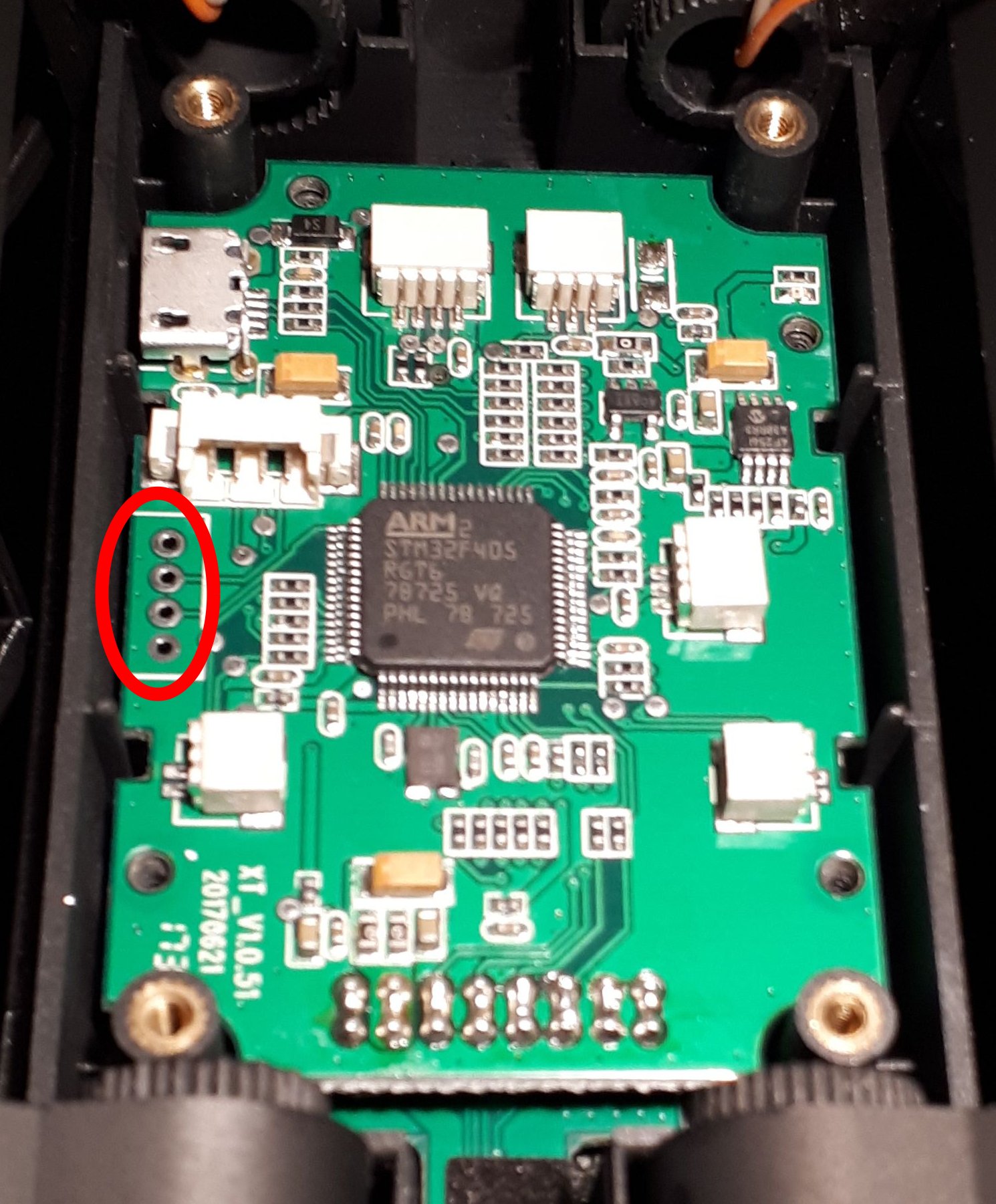
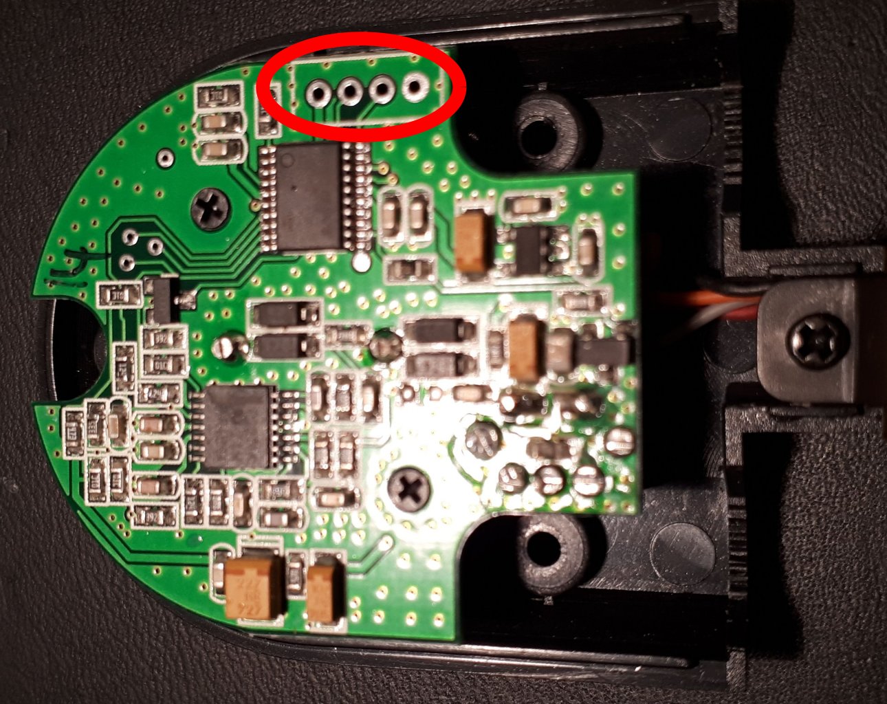
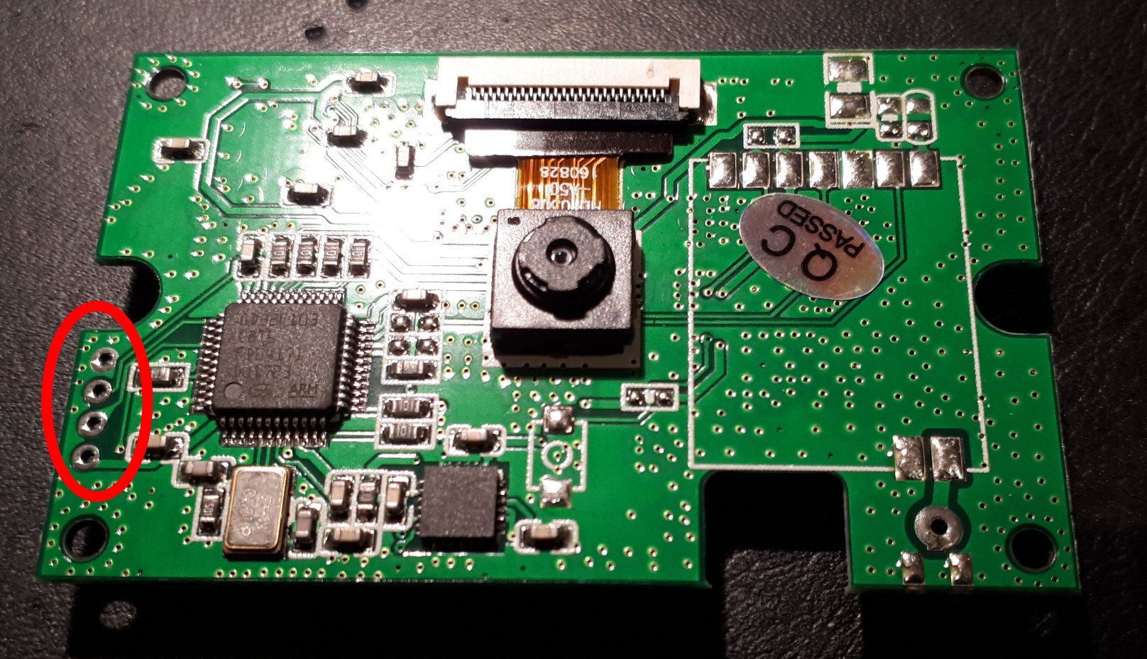
But the best of it all: The FMU, flow and distance sensor each have a four pin header footprint running some traces towards the MCUs.
A quick check with my programmer put a big smile on my face: The connectors were SWD programming ports! The flash memories being locked, though, but only to the first level, so reading was not allowed, but the MCUs were still programmable. Wow.
The new idea was: Could this STM32F405 FMU run my favorite open source flight control software PX4? The internet says it can and even though the MCU might be a bit small, there are even official and open source projects based on the very same Chip – Outdated, but still alive, so I decided to dig a bit deeper into the hardware.